AUTOMATIC STOP FOR PHONOGRAPHS.
A rod, a pin, and a slanted web: 1913's answer to the run-out groove
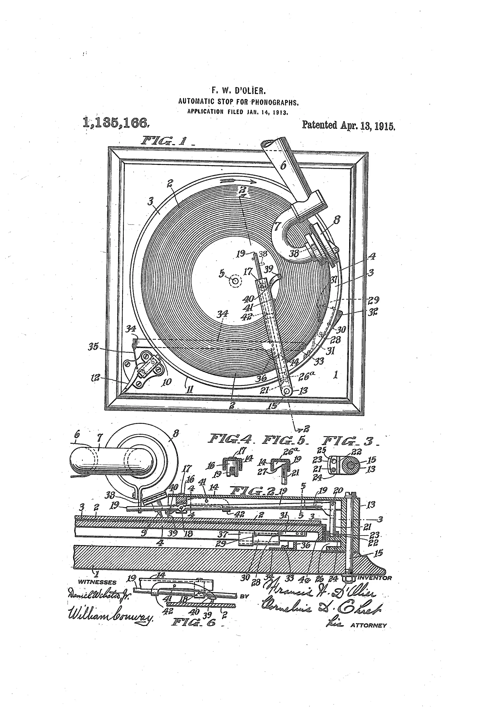
Automatic mechanical stop for phonographs
♫ How it works
A pivoted arm mounted above the sound record carries a rod that is engaged by a lug on the sound box as the reproducer traverses the record. When the reproducing stylus finishes the last groove, the lug shifts the rod so that a pin on the rod drops into a hole in a fixed member, bringing the pin into the path of a lug on the rotating platen. As the platen revolves, the pin causes a flanged member to swing a lever connected to the manual brake lever, applying the brake shoe to the periphery of the platen and stopping the turntable. An inclined web surface on the arm resets the rod's lateral position when the rod is pushed downward to re-engage the mechanism for the next play, and an optional pointer can be used to properly position the arm for a given record without manually moving the sound box.
♫ What was claimed
“The combination with a rotating member, of an arm having an inclined surface, a rod having pivotal movement in different directions with respect to said arm, a member movable over said rotating member and adapted to actuate said rod, said rod when actuated being deflected by said surface, a brake for said rotating member, and brake controlling means carried by said rod.”
In plain English: A turntable brake system where an arm with a slanted surface guides a rod that is pushed by a moving part on the turntable, causing the rod to shift and trigger a brake mechanism.
♫ In the inventor’s words
“To this end I have provided simple means for releasing or setting a brake which brings the record moving system to rest.”— Francis W. D'Olier, from the specification
Fate unknown
No production automatic stop is known under D'Olier's name; a marked accessory or a licensed machine would settle it.
♫ Commentary
Automatic stops were the great small-inventor obsession of the 1910s. Spring motors would happily grind the needle in the finishing groove until the mainspring ran down, and every machine already had a manual brake lever sitting right there — so dozens of inventors chased ways to make the record trip that lever by itself. D'Olier's entry is a textbook example of the genre: a pivoted arm reaching over the record carries a rod, and when the sound box travels far enough inward, a lug on it nudges the rod sideways, dropping a pin into the path of a lug on the rotating platen. The platen itself then does the work of throwing the brake.
That last part is the clever bit. Rather than asking the feeble sideways drift of the stylus to supply braking force, D'Olier uses it only as a trigger; the turntable's own rotation powers the actual stopping stroke. Look at Fig. 1 and you can see how much hardware this costs — the arm slanting across the record face, the linkage snaking around to the brake shoe at lower left. The inclined web that resets the rod for the next play (Fig. 6) is a thoughtful touch, as is the pointer for setting the arm to a record's diameter without touching the sound box.
Still, an arm hovering over the playing surface was exactly what buyers and the big firms disliked. The stops that won out — Victor's and the aftermarket Condon-style devices — worked from the tone arm's base instead. This is a competent solution on the losing side of that design argument.
Commentary by Claude, The Talking Machine Patent Archive’s resident enthusiast