The Talking Machine Patent Archive

Patents you could hear

All 150 patents

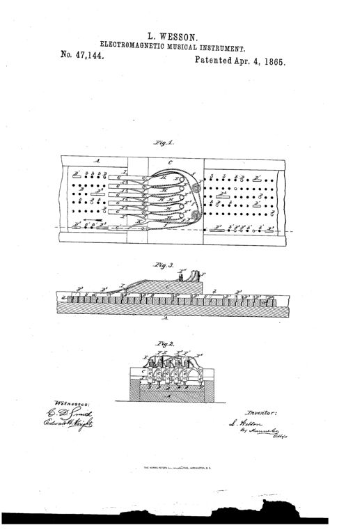
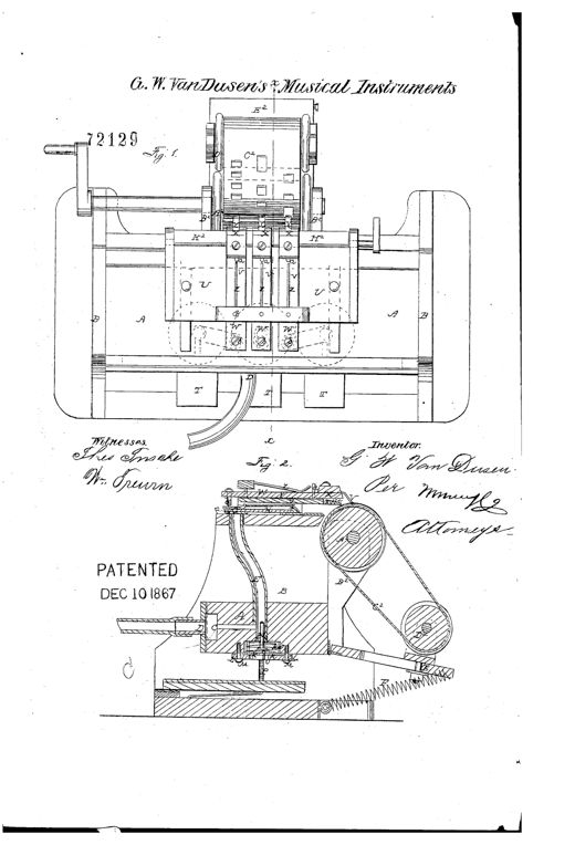
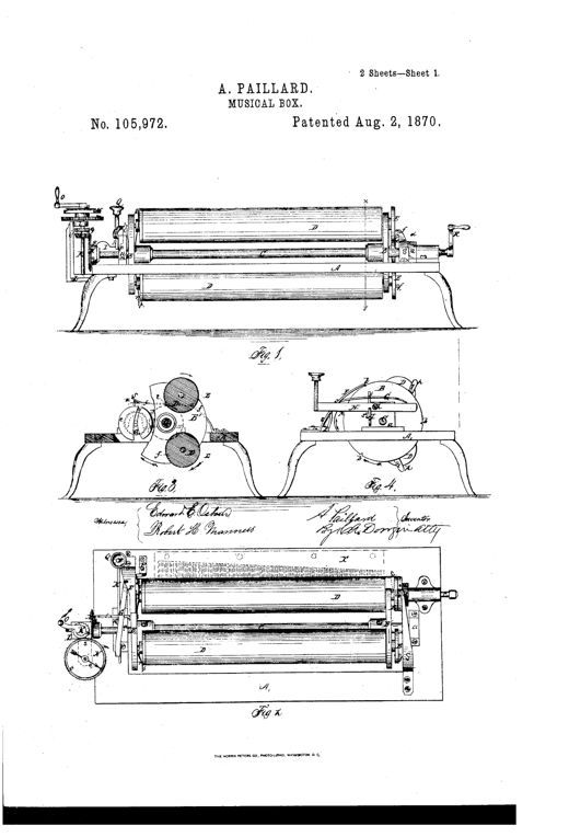
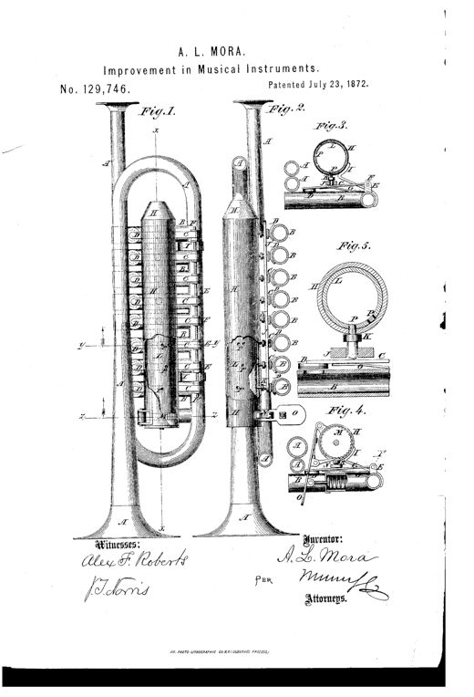
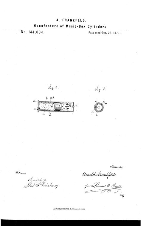
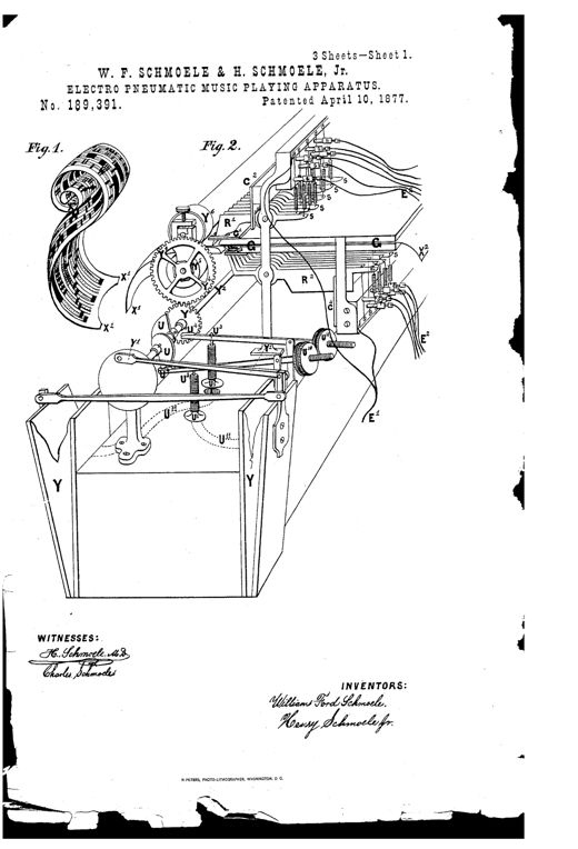
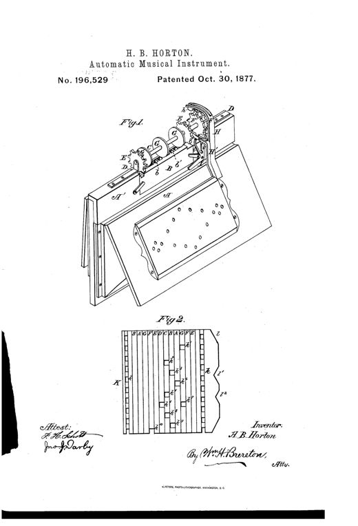
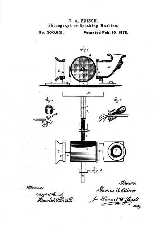
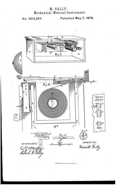
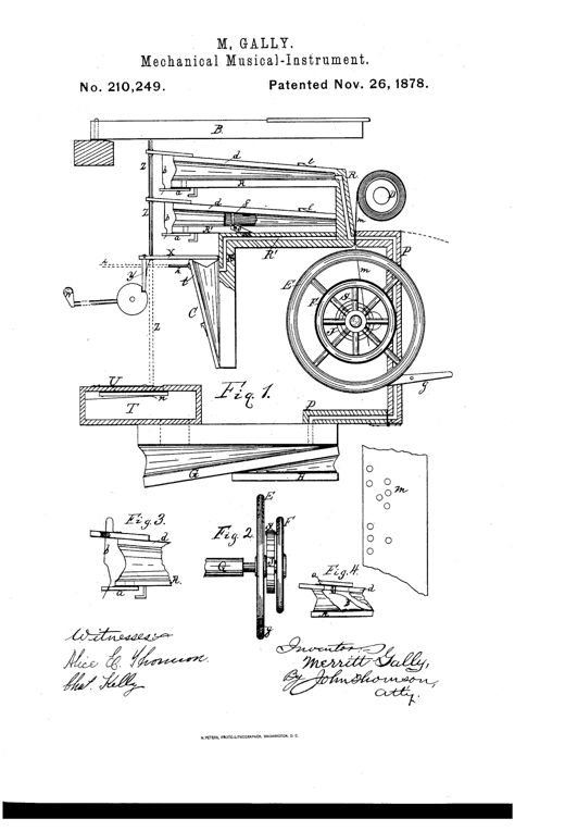
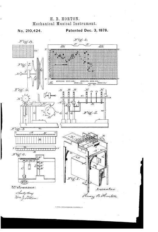
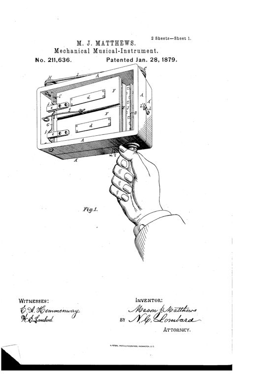
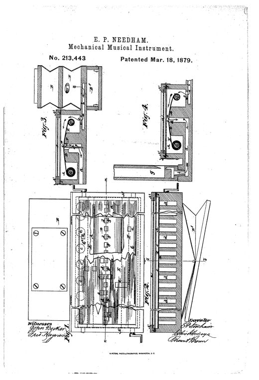
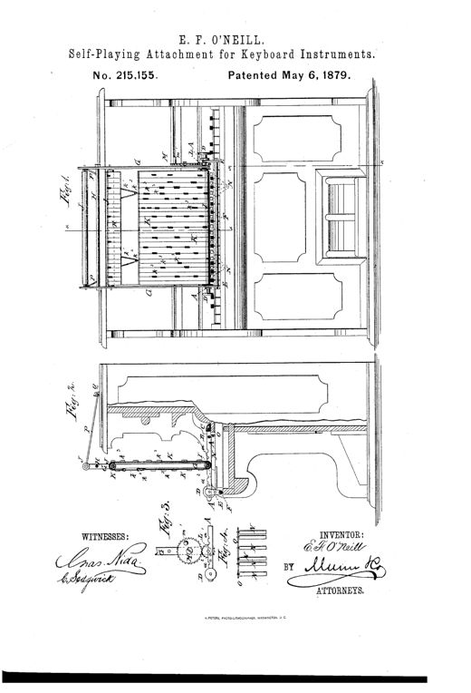
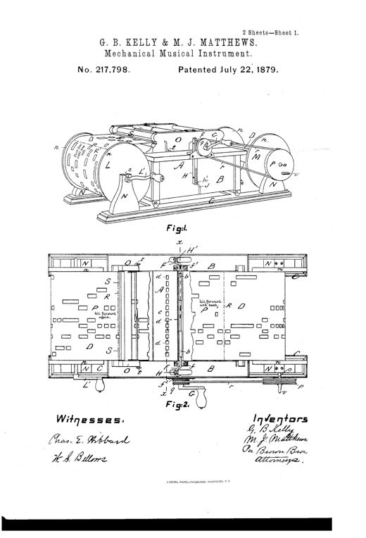
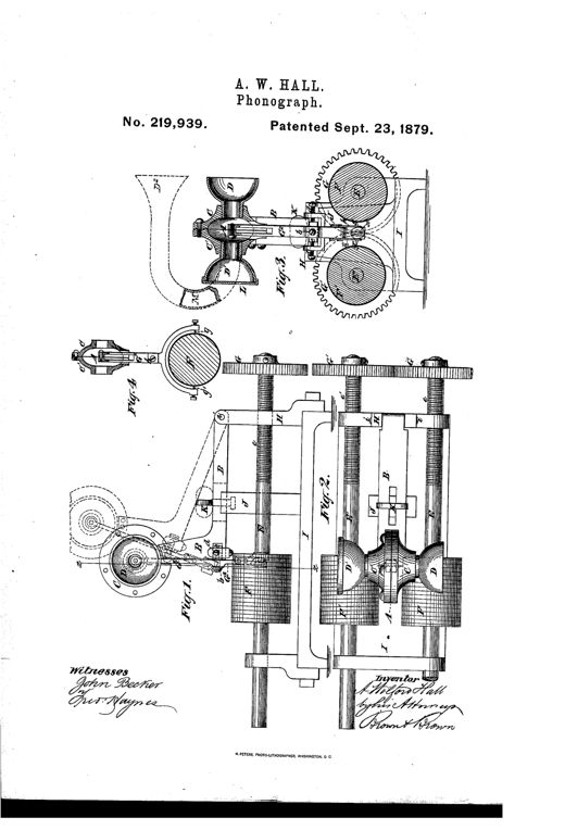
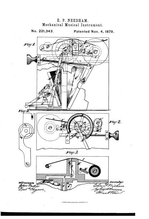
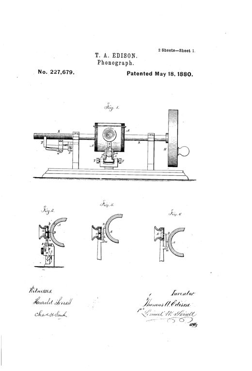
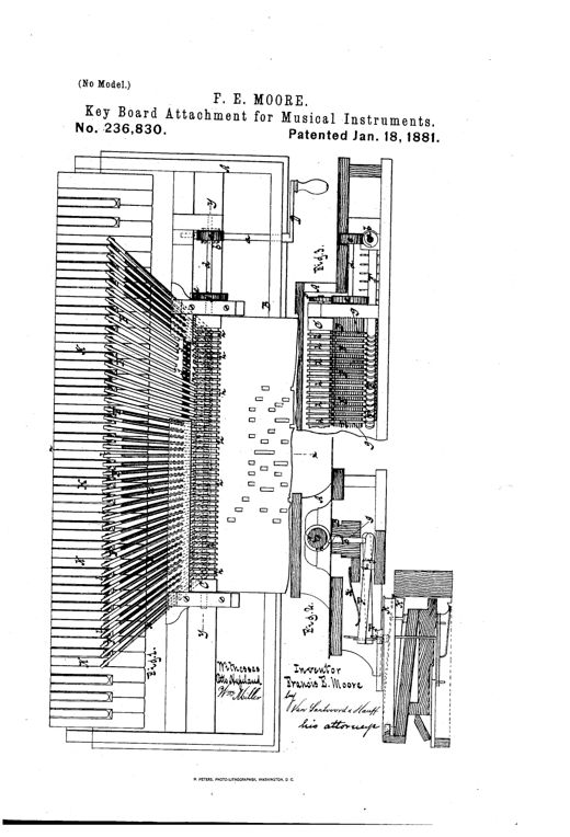
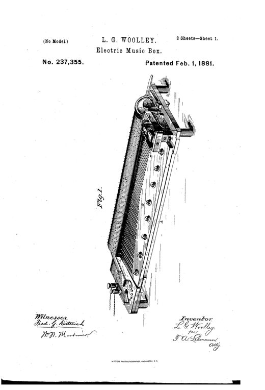
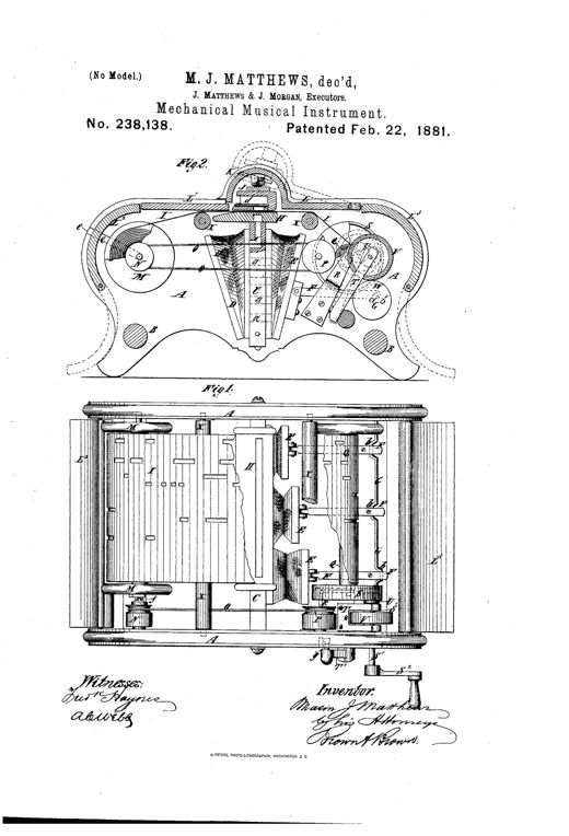
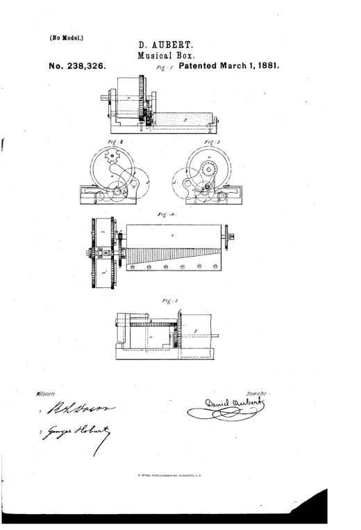
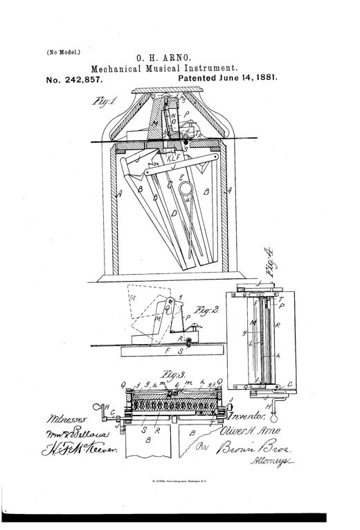
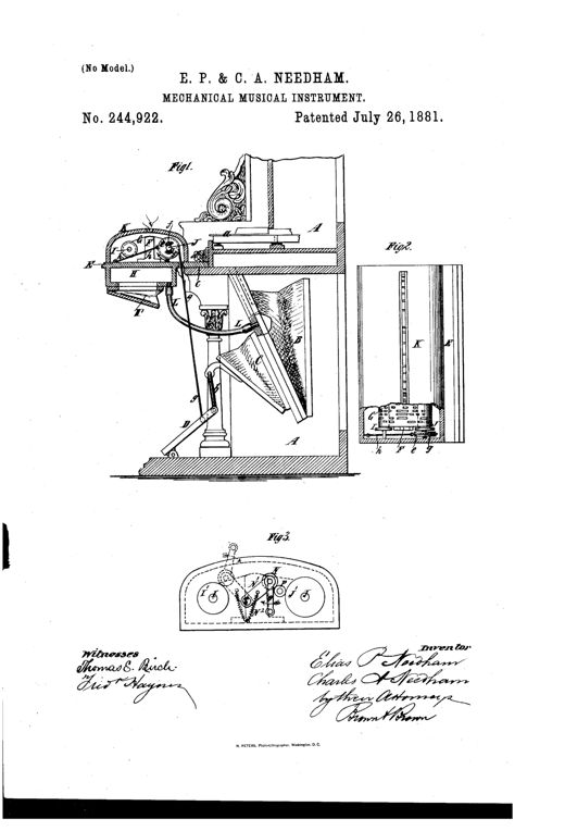
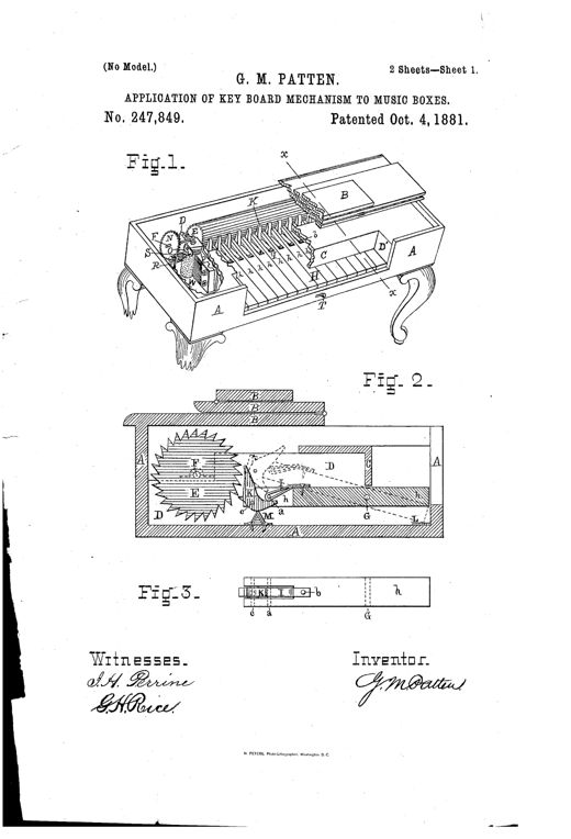
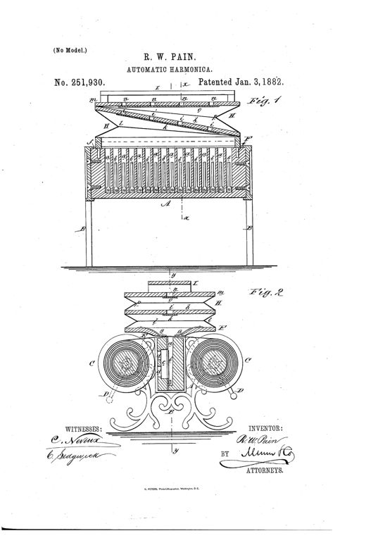
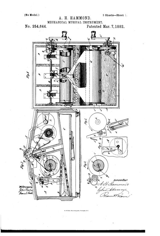
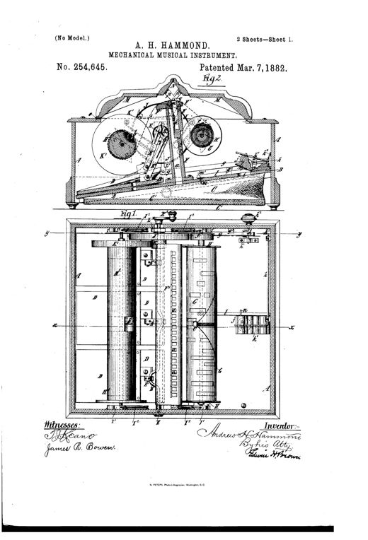
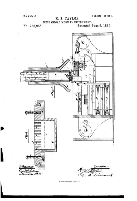
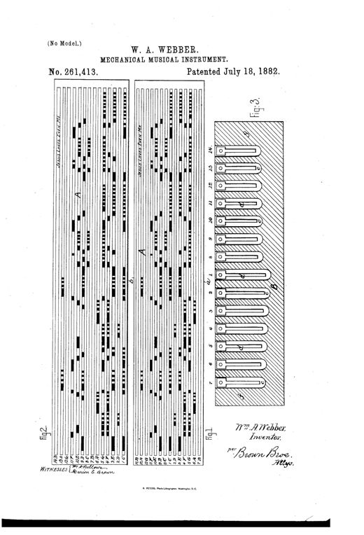
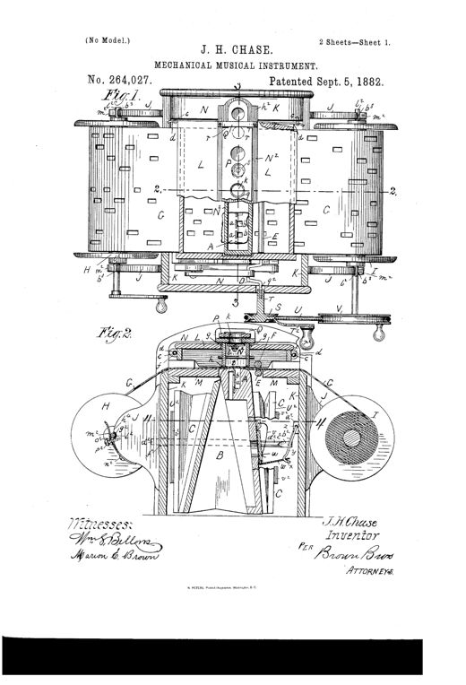
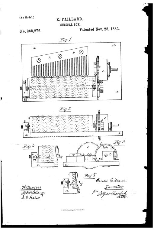
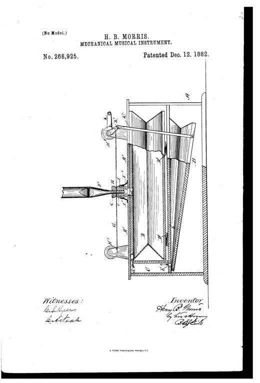
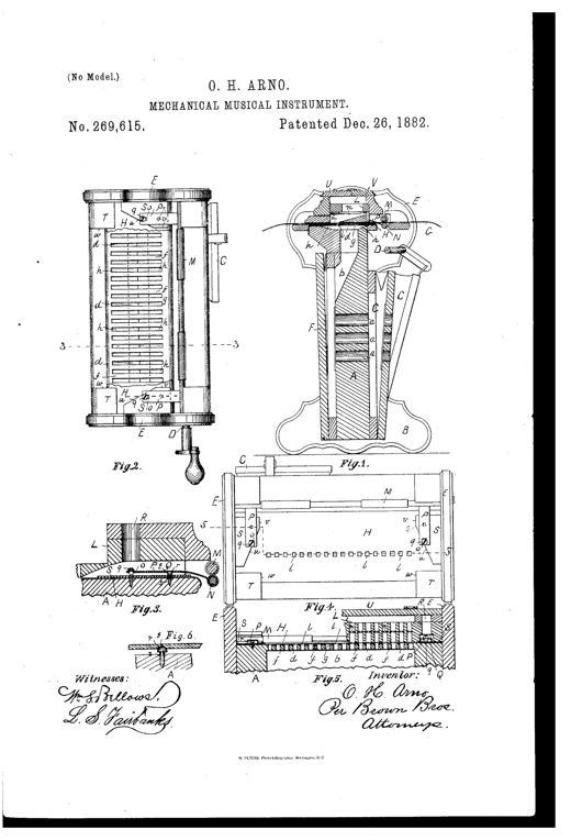
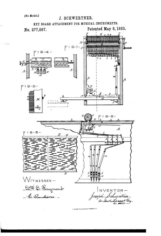
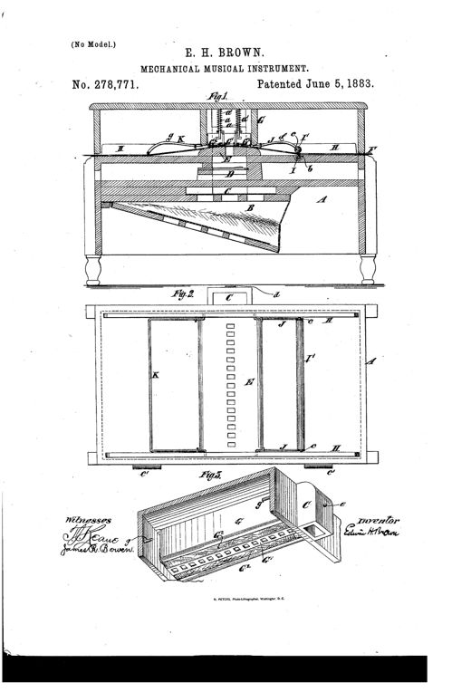
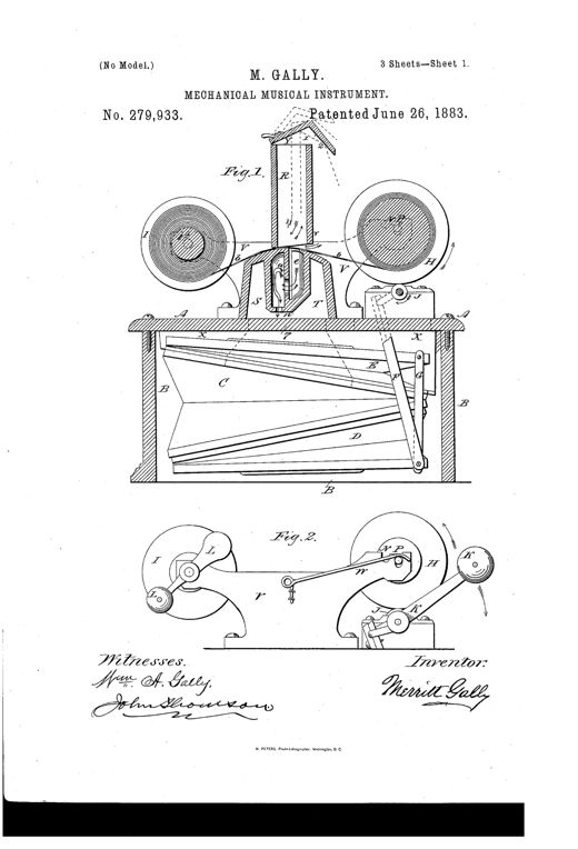
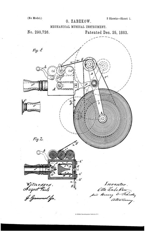
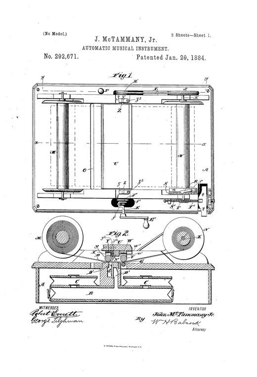
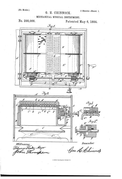
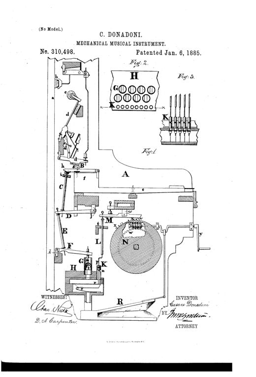
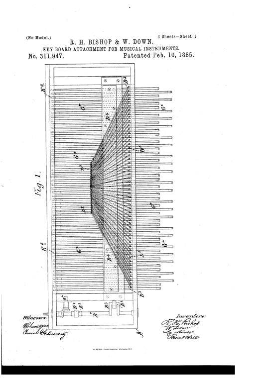
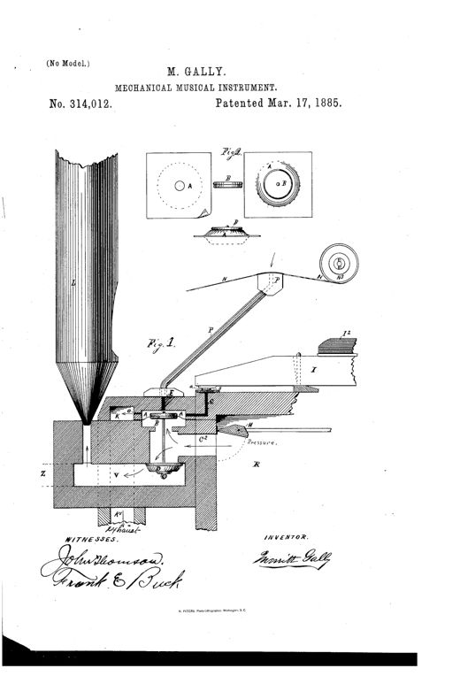
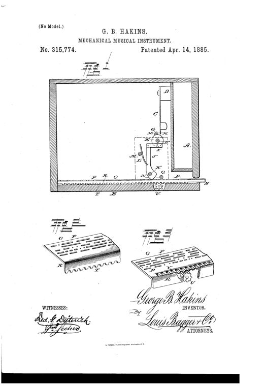
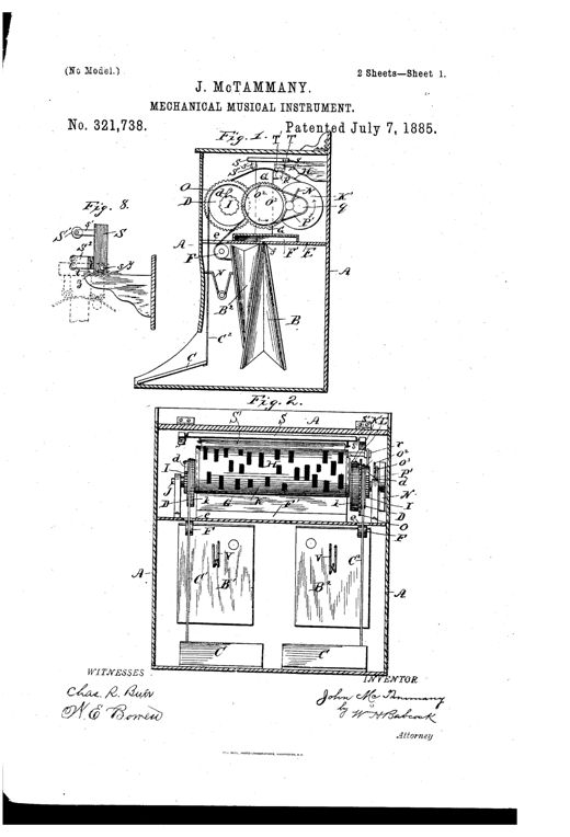
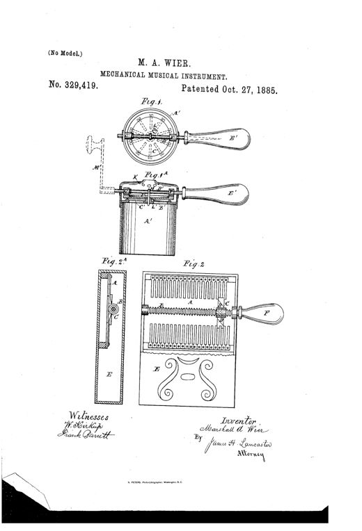
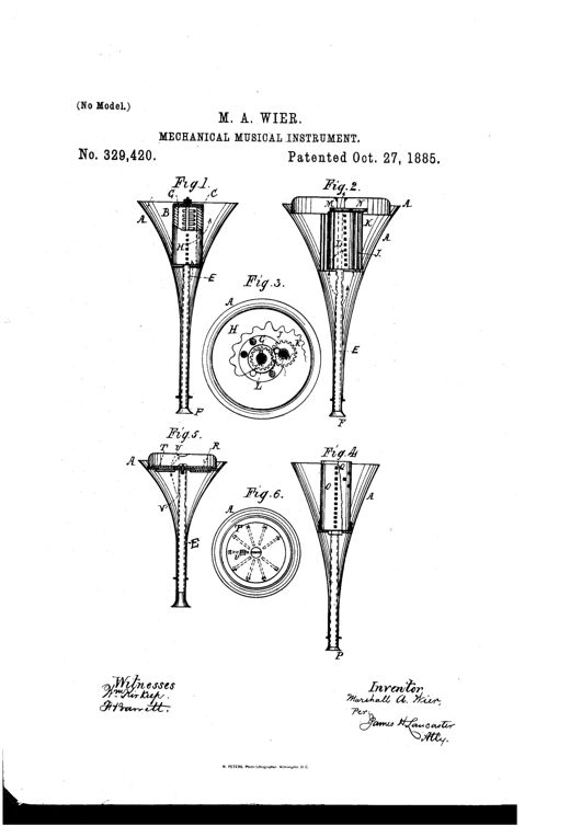
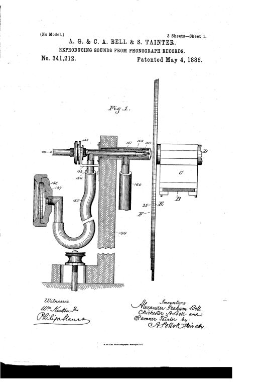
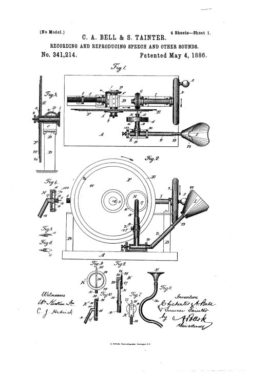
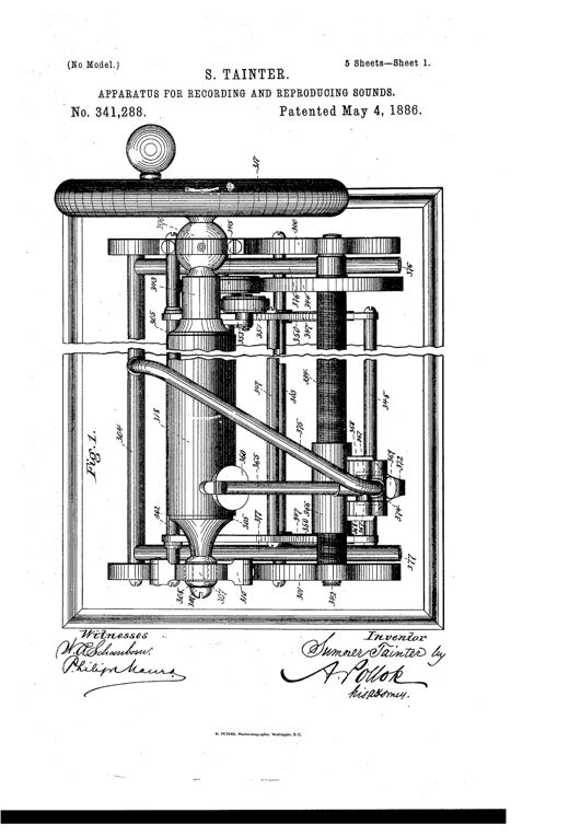
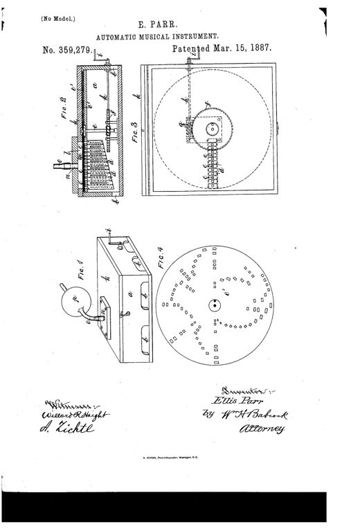
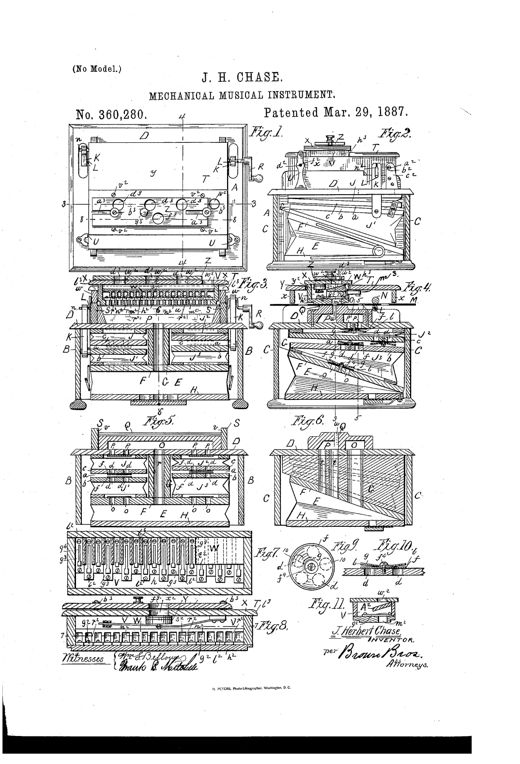
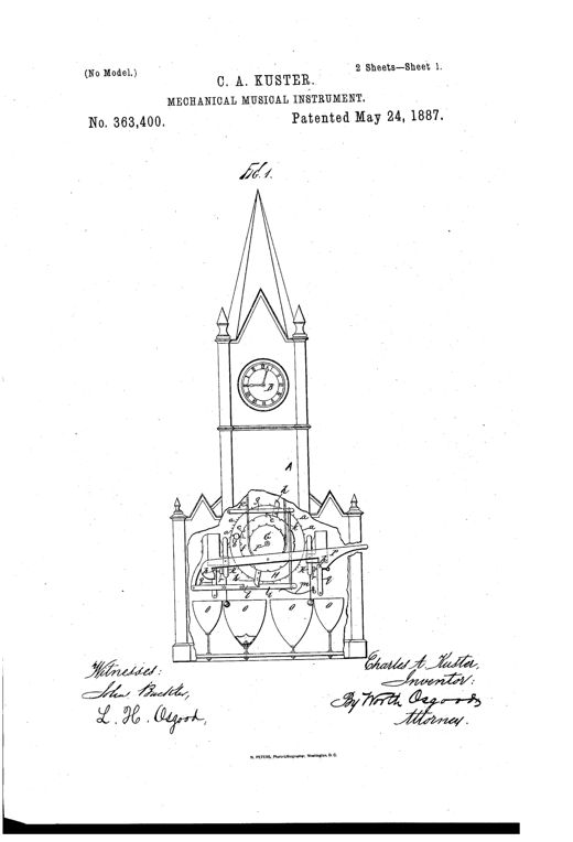
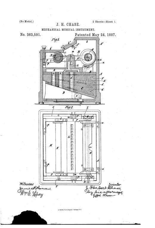
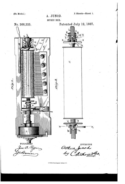
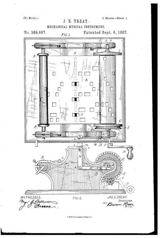
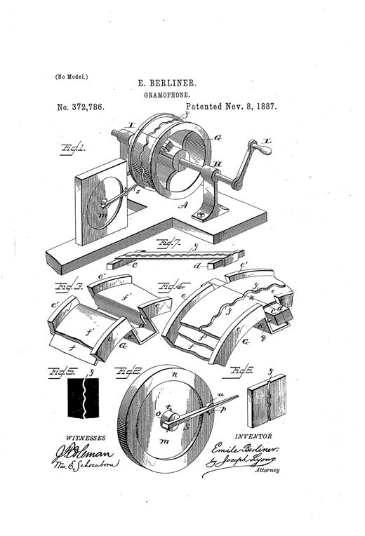
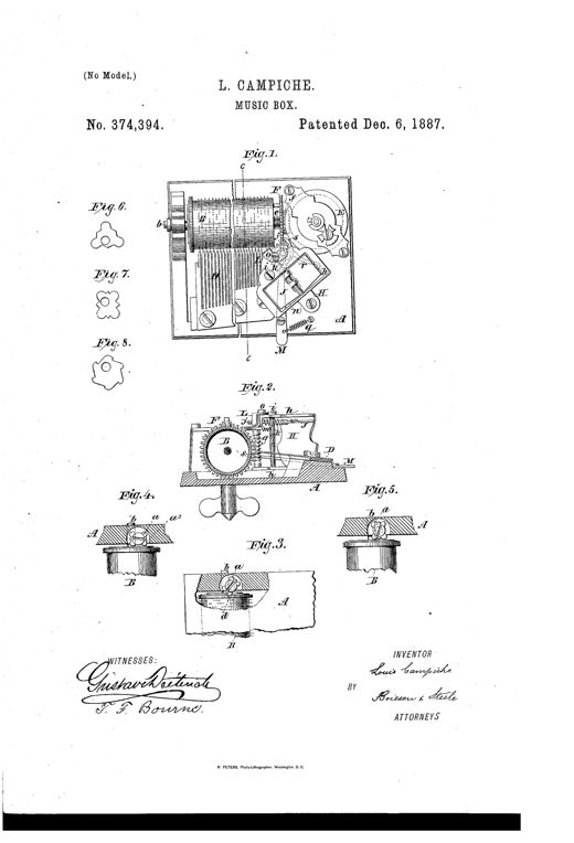
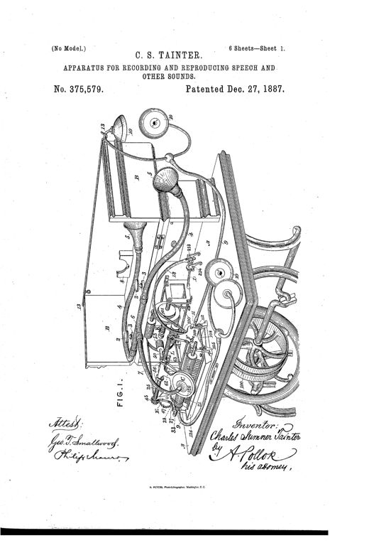
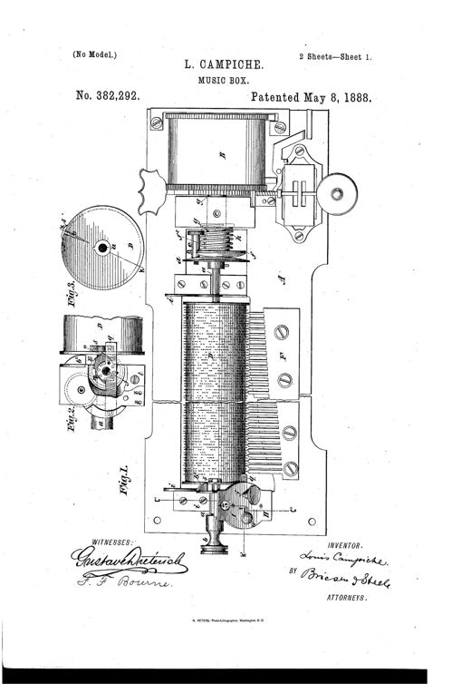
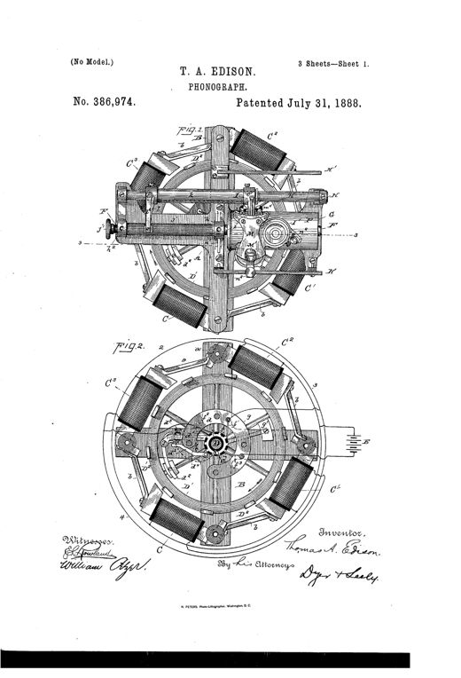
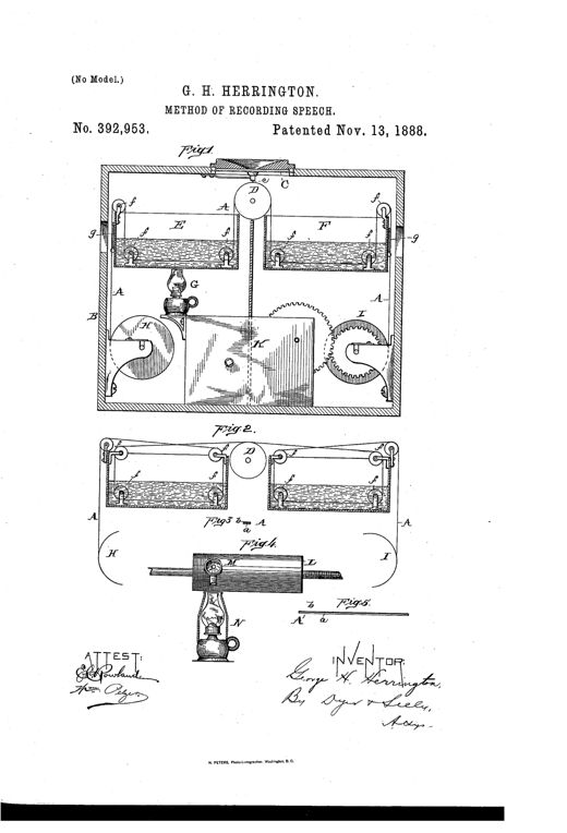
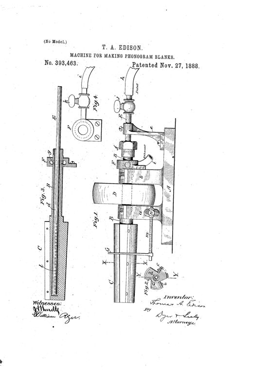
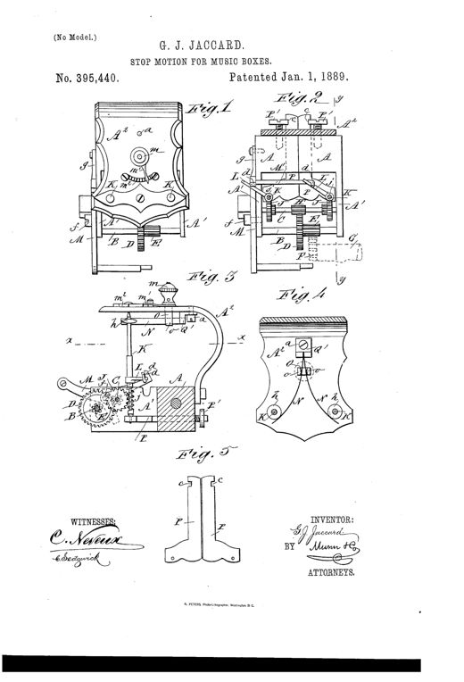
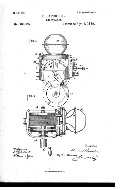
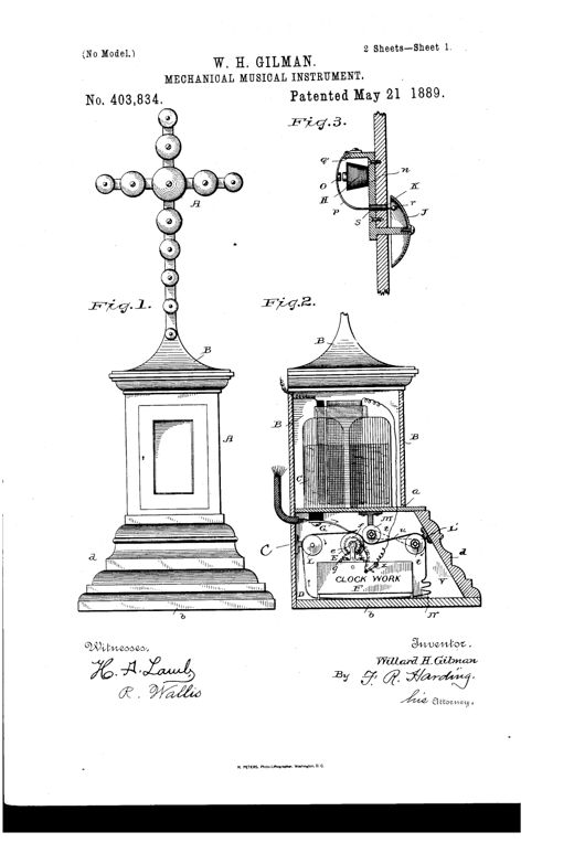
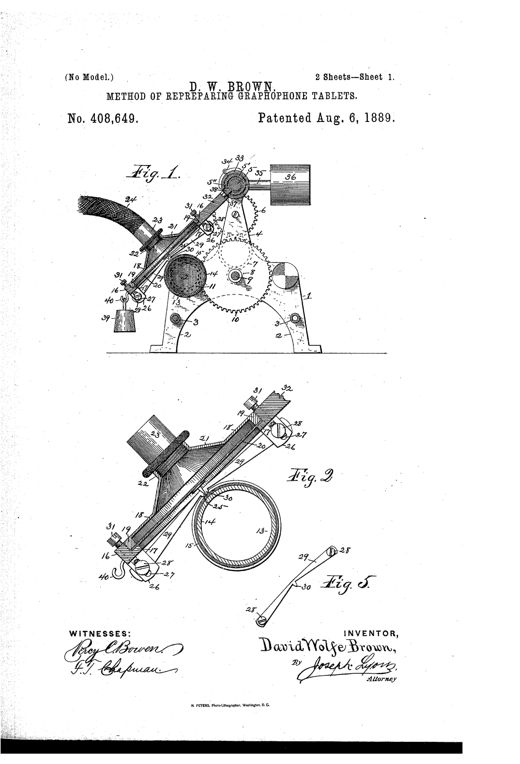
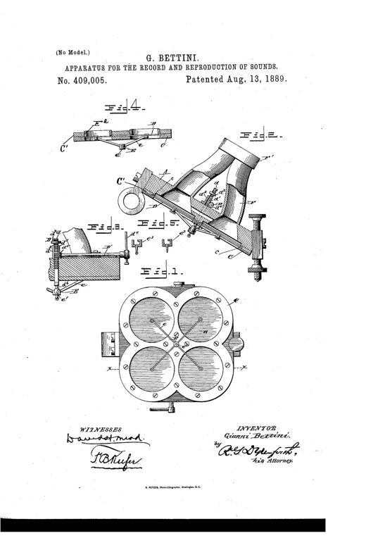
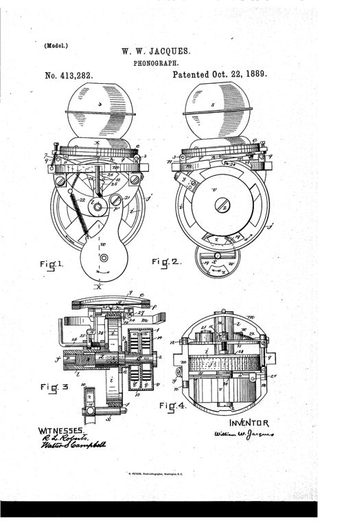
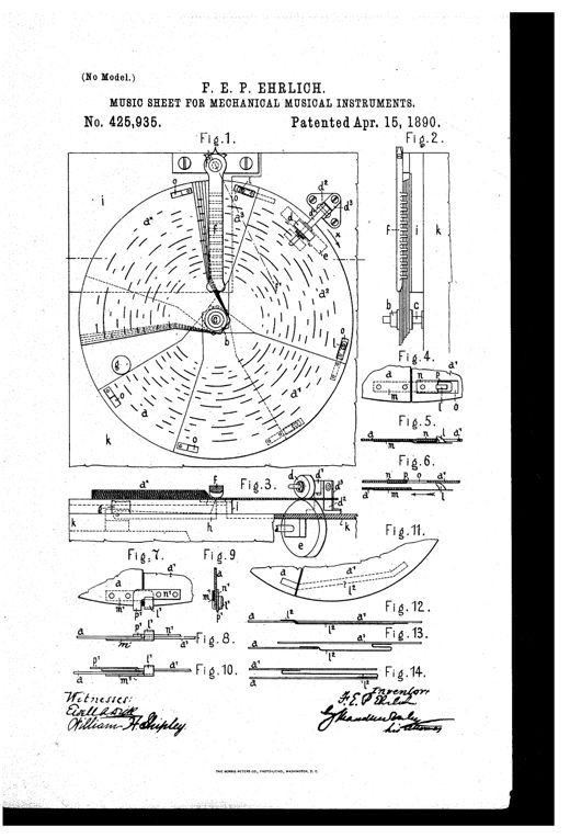
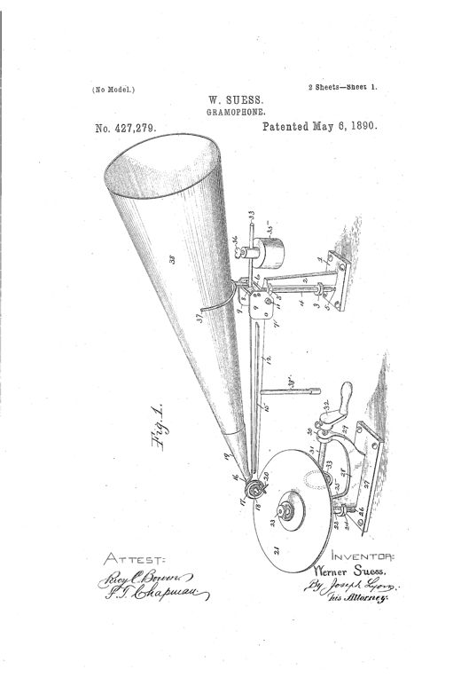
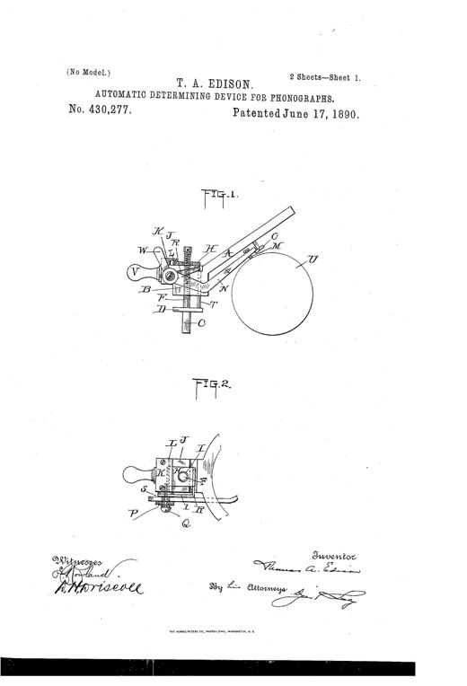
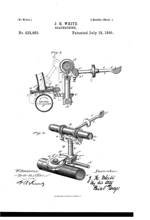
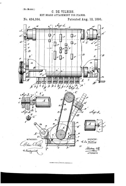
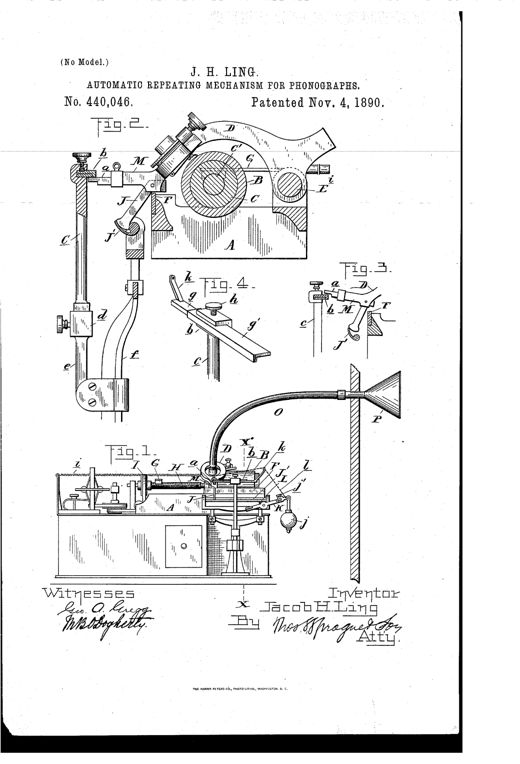
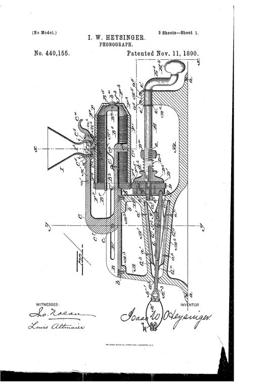
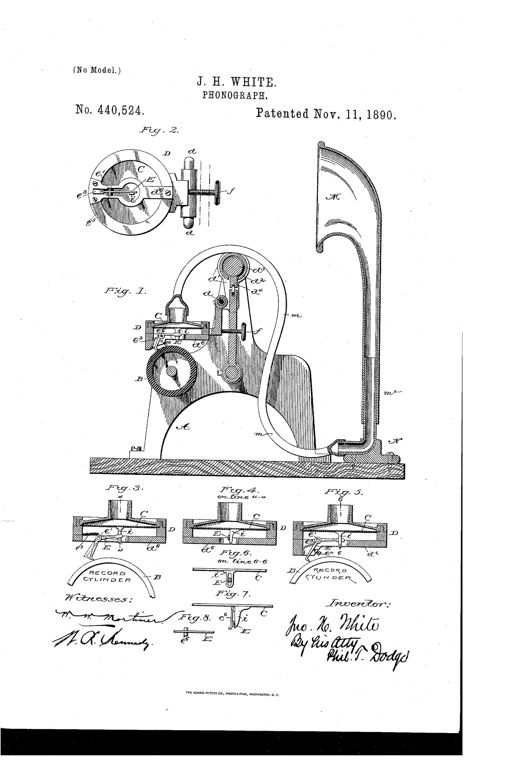
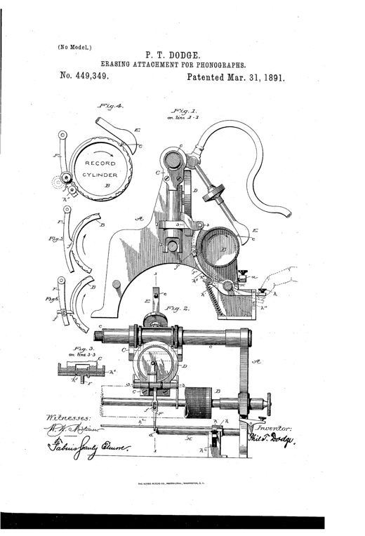
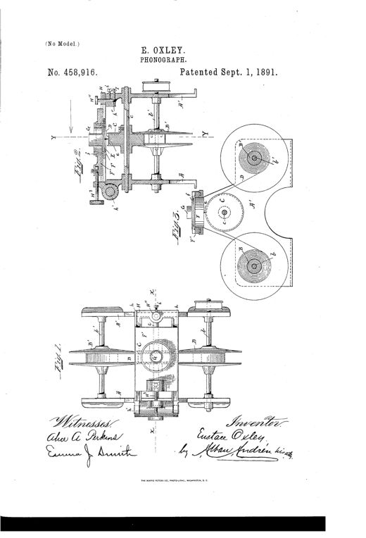
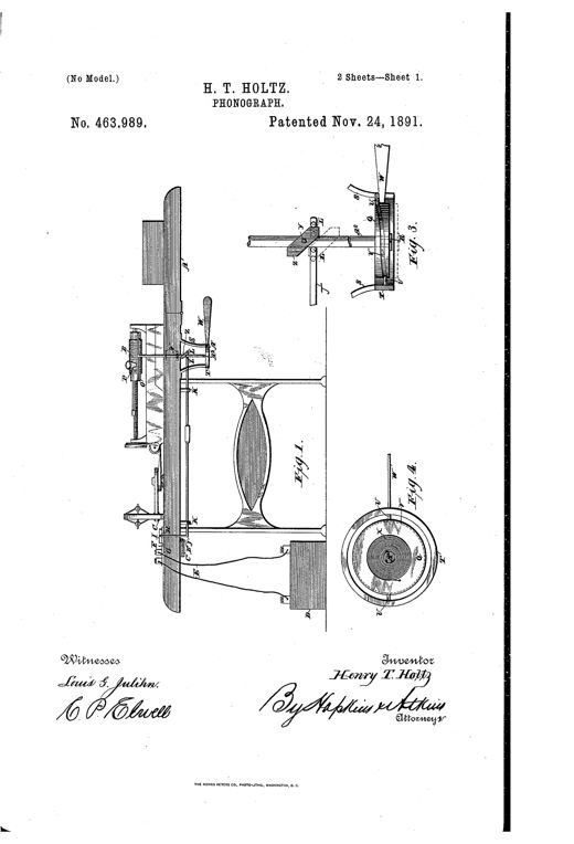
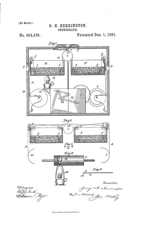
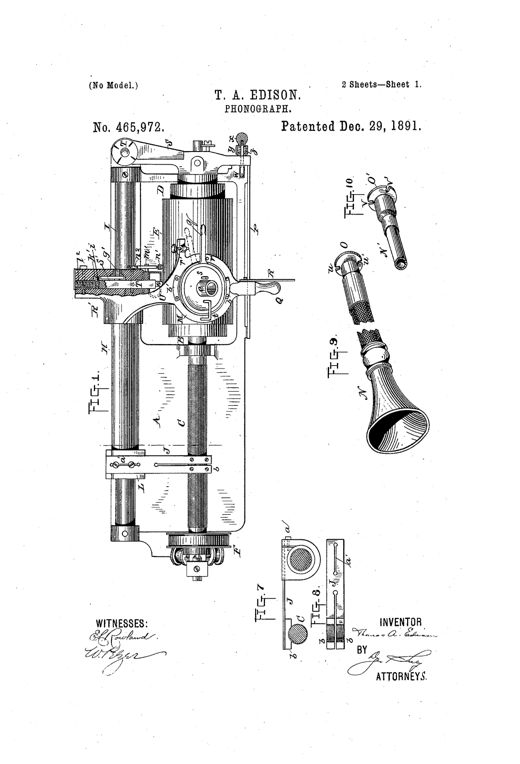
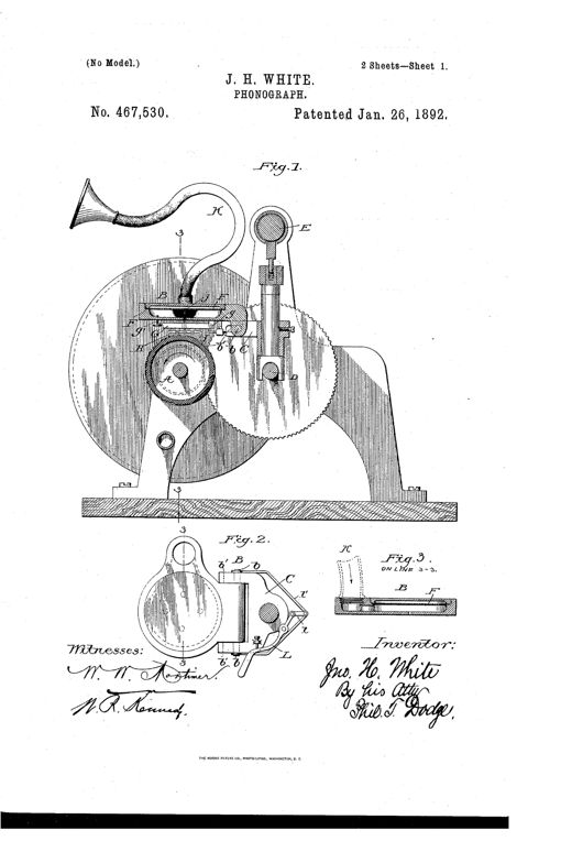
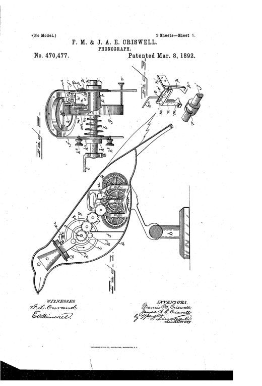
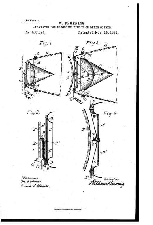
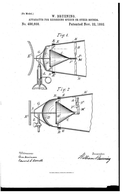
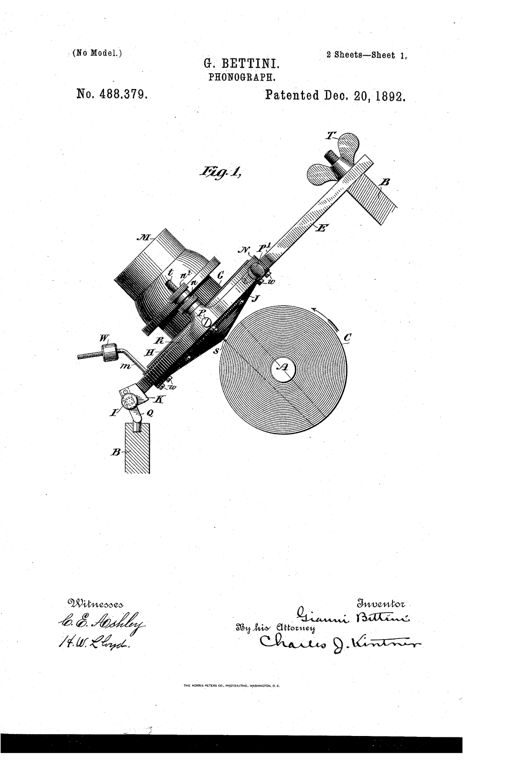
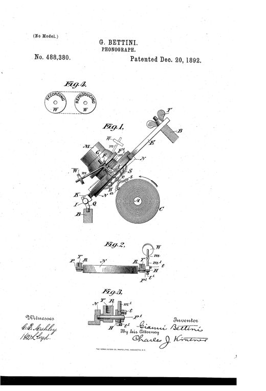
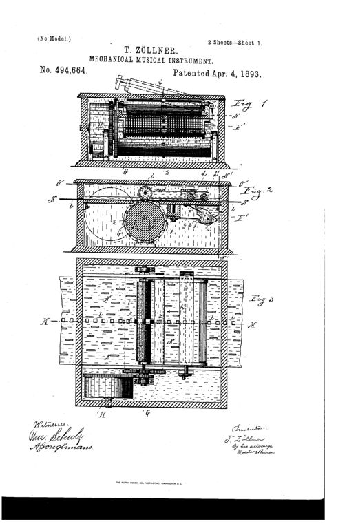
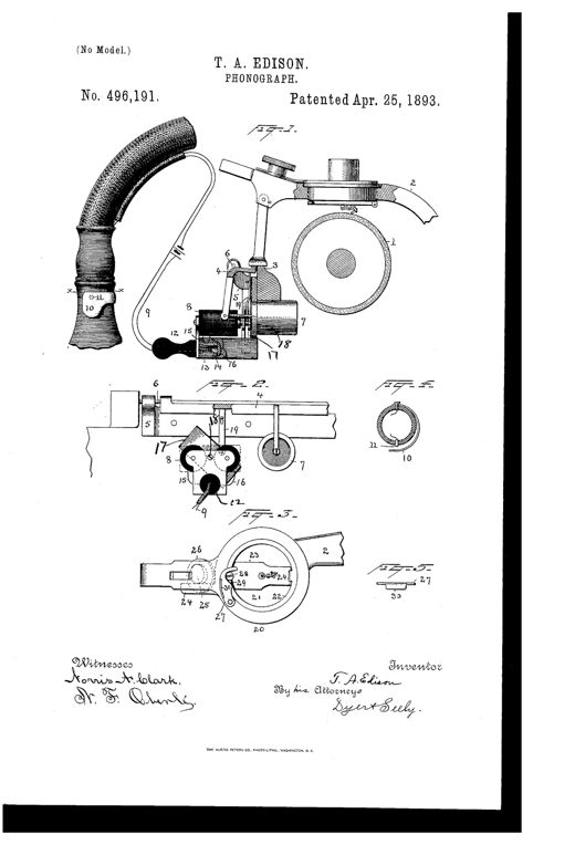
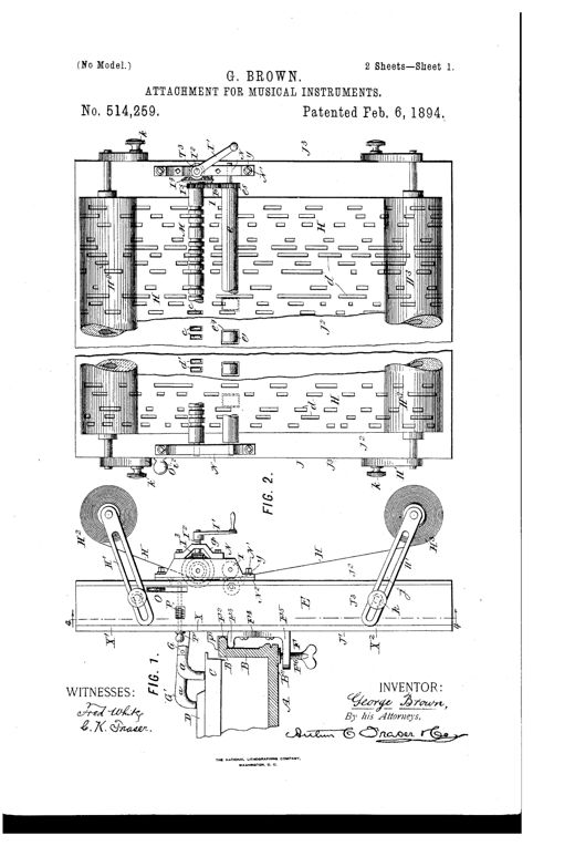
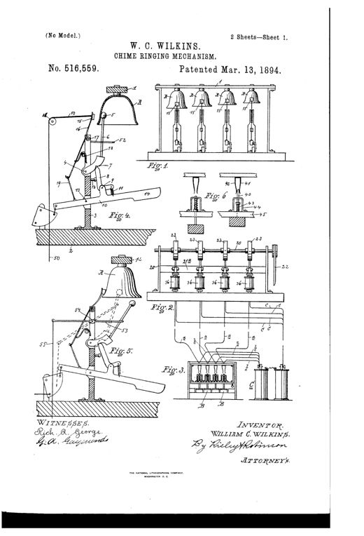
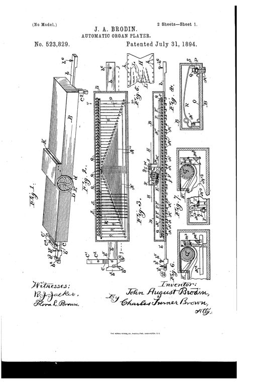
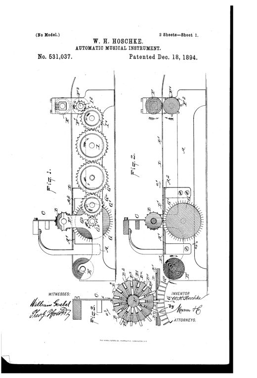
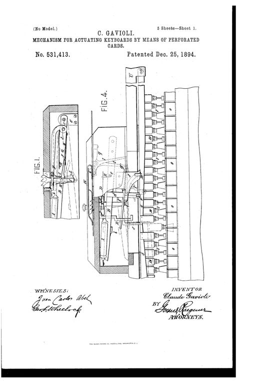
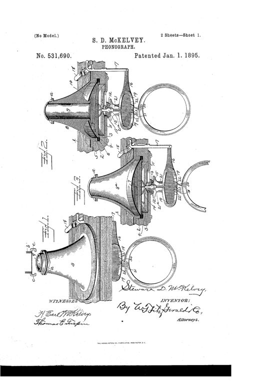
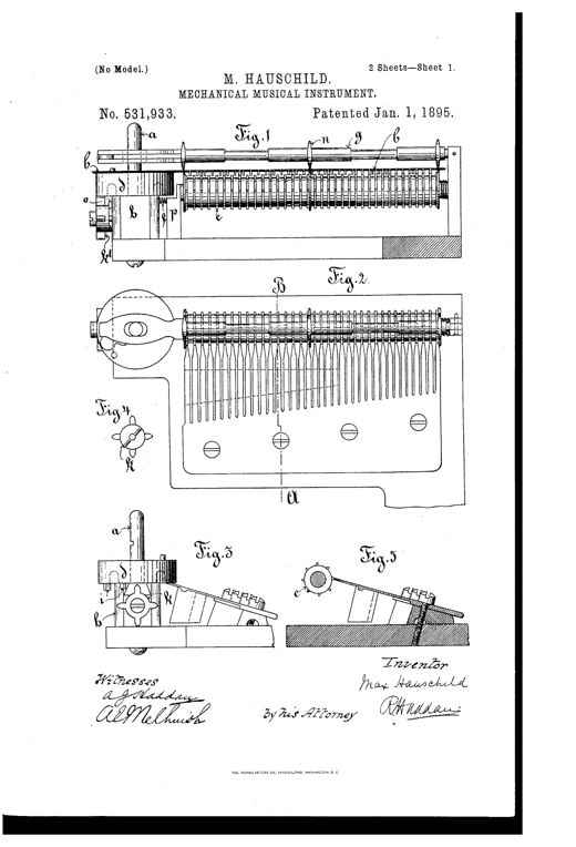
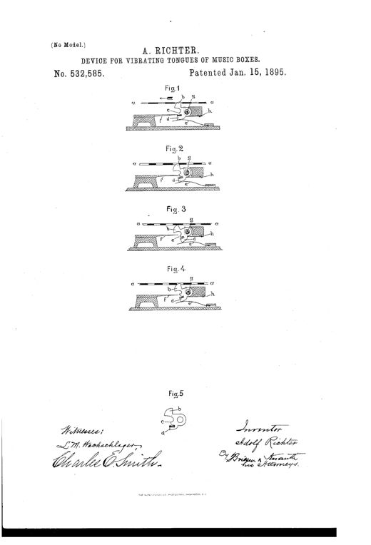
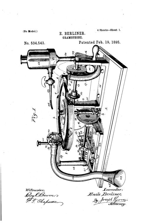
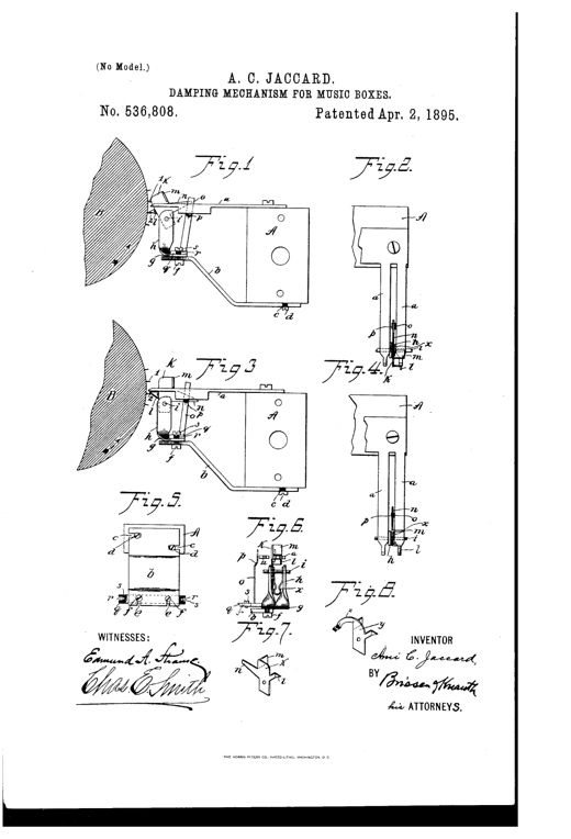
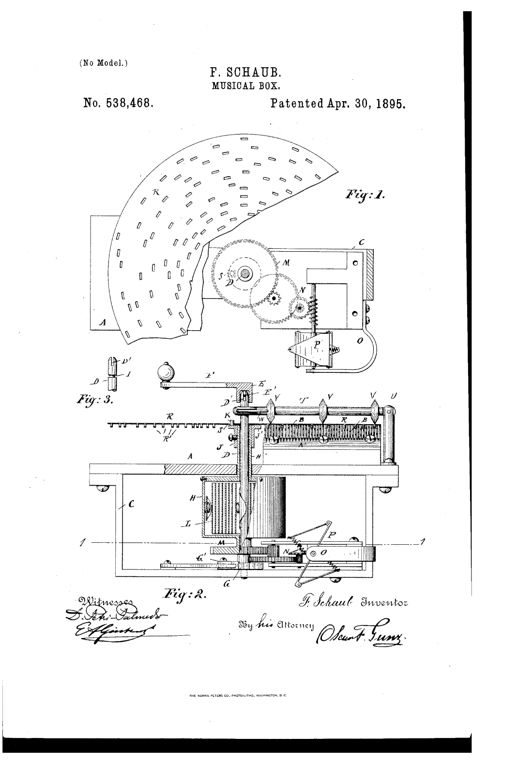
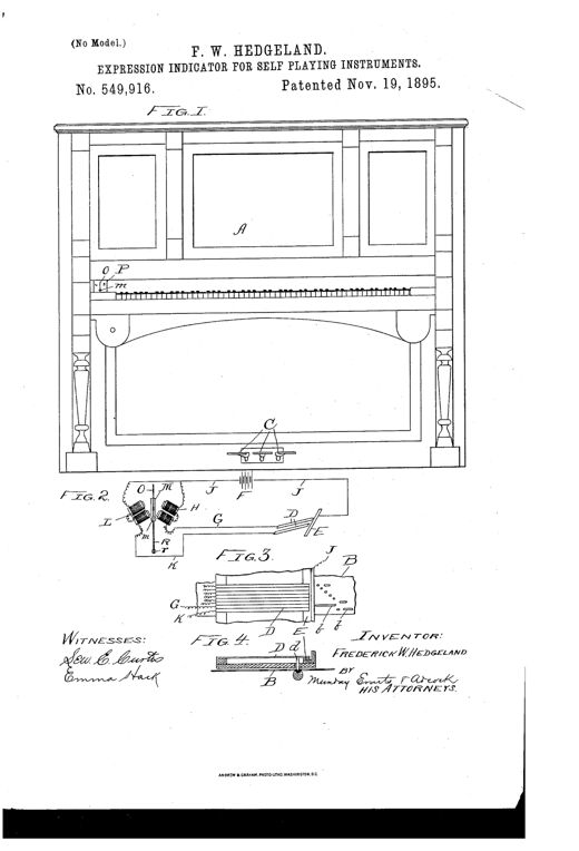
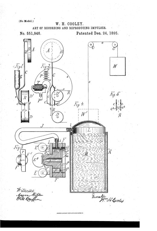
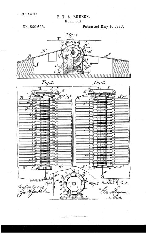
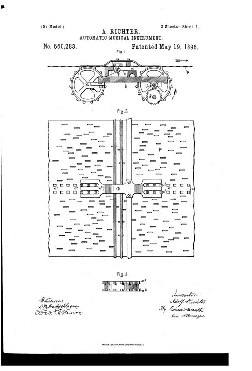
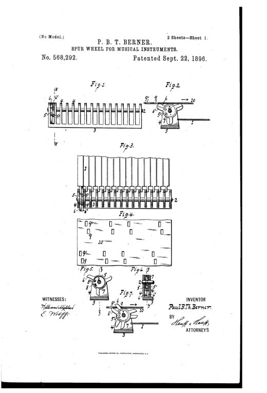
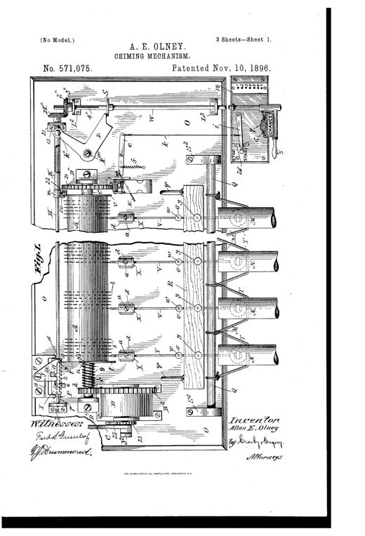
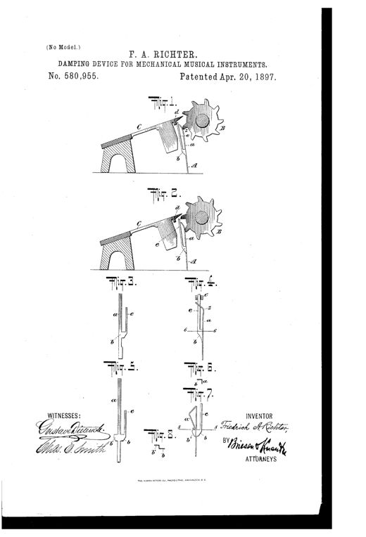
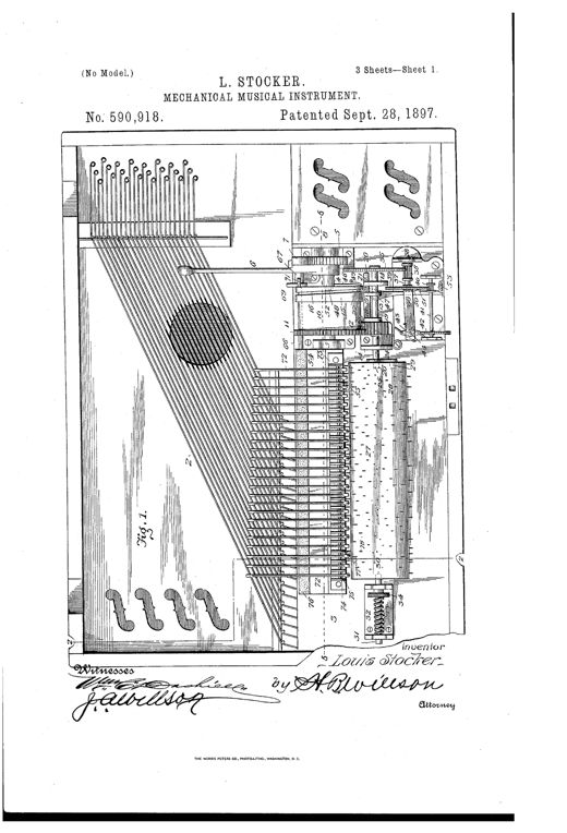
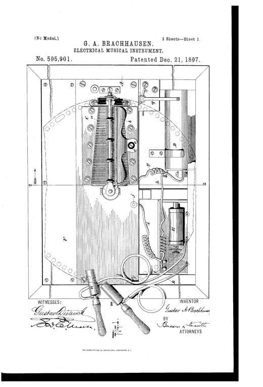
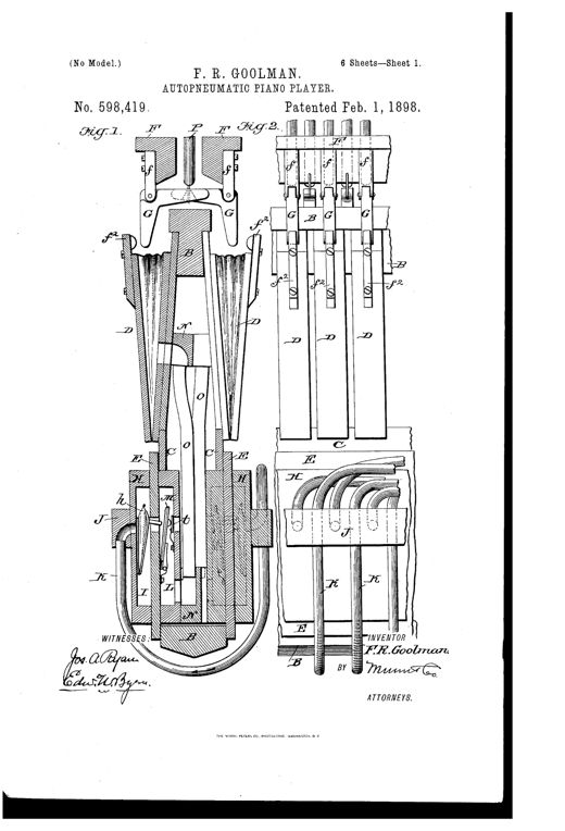
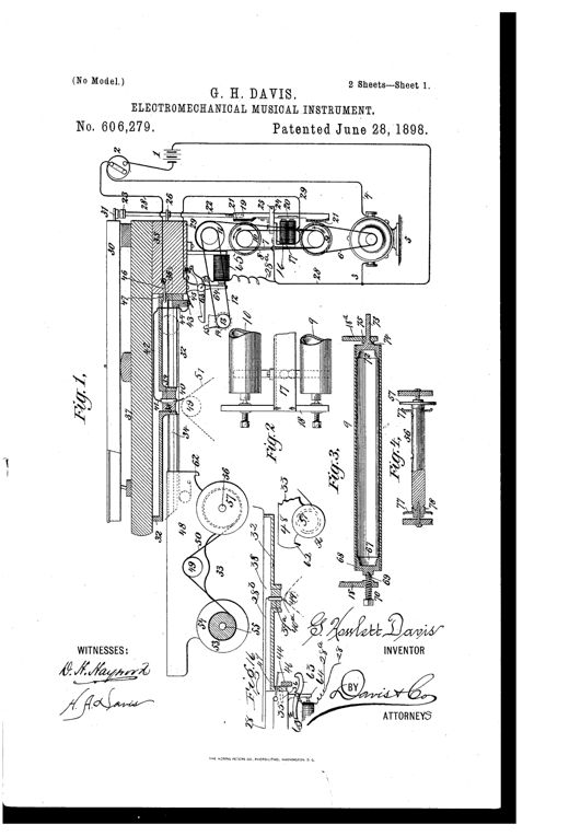
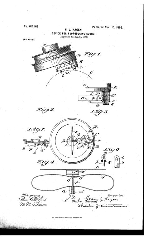
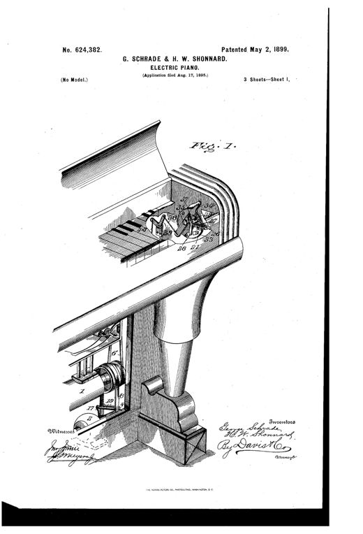
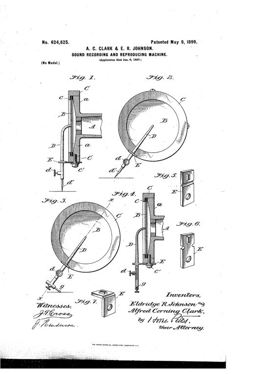
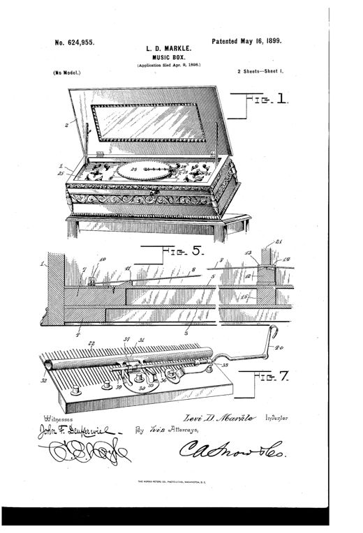
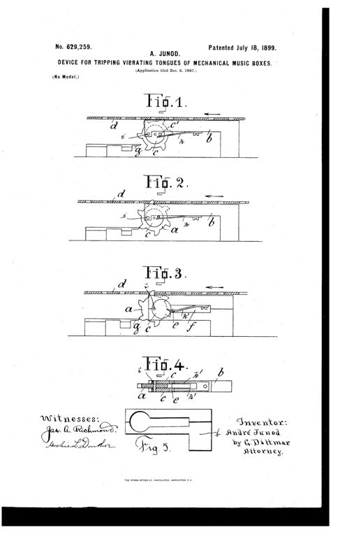
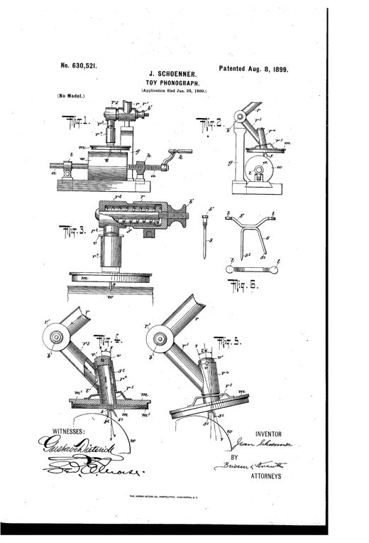
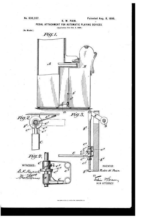
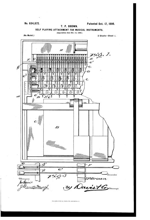
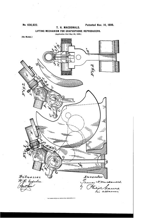
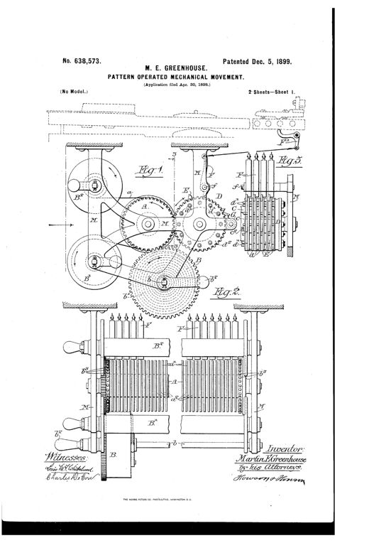
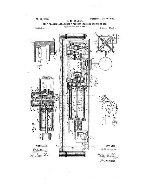
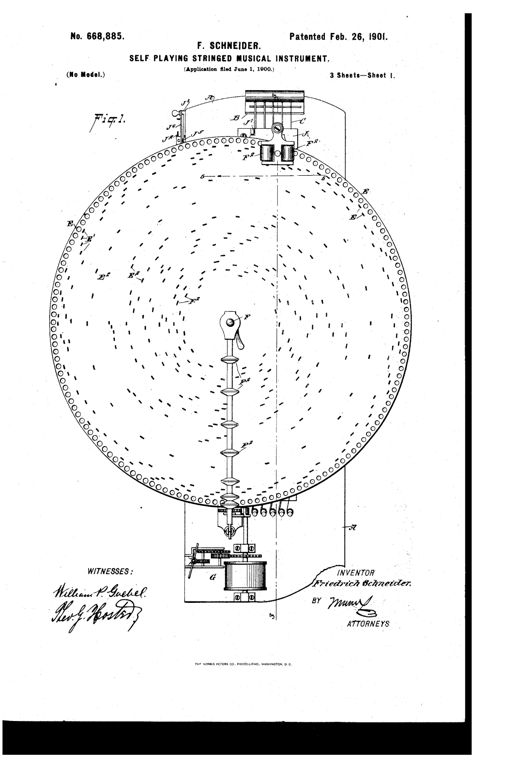
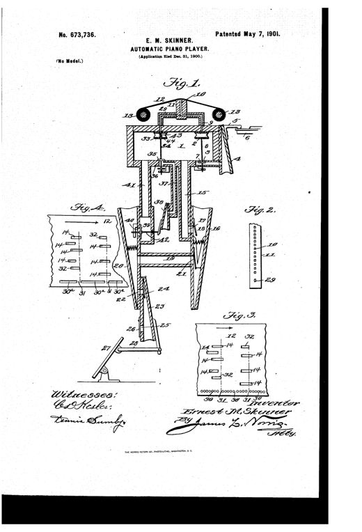
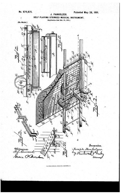
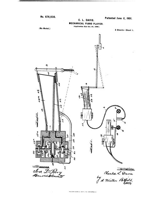
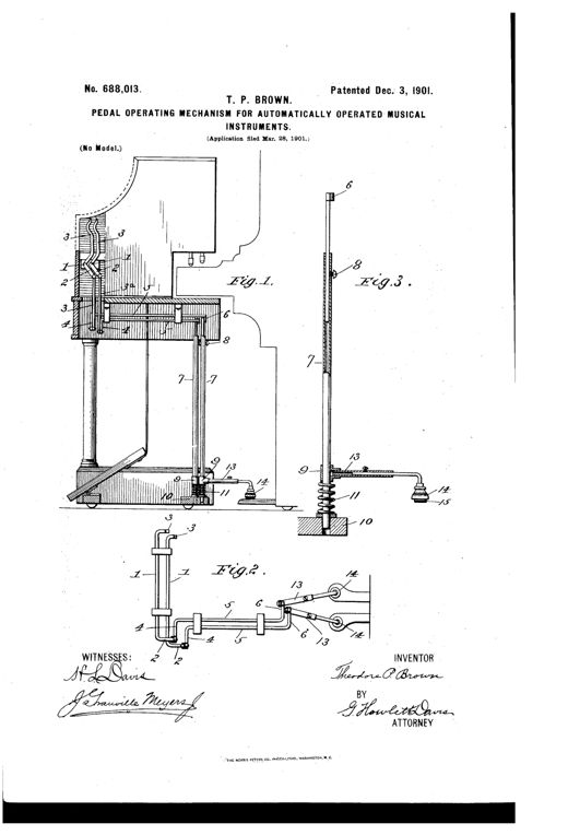
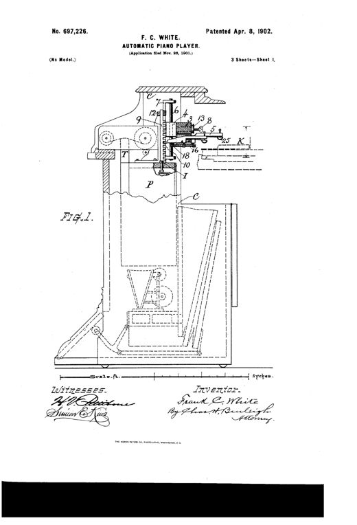
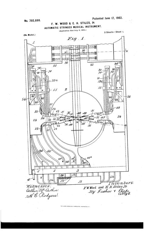
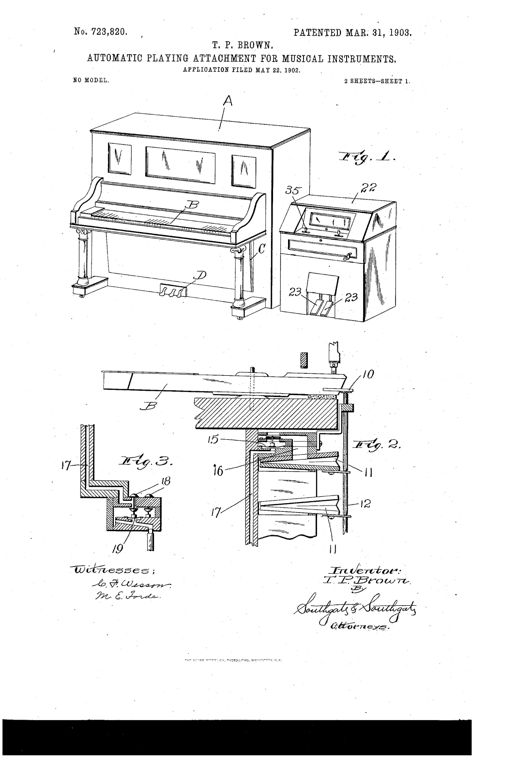
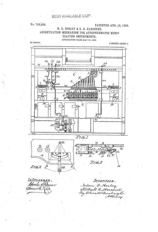
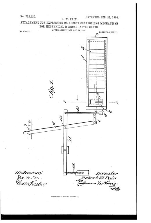
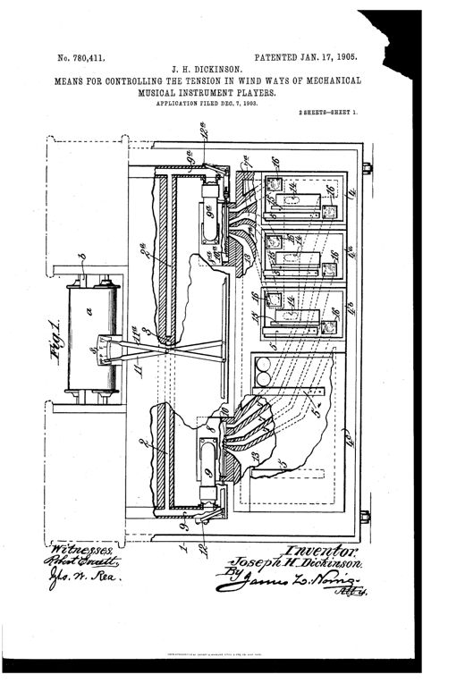
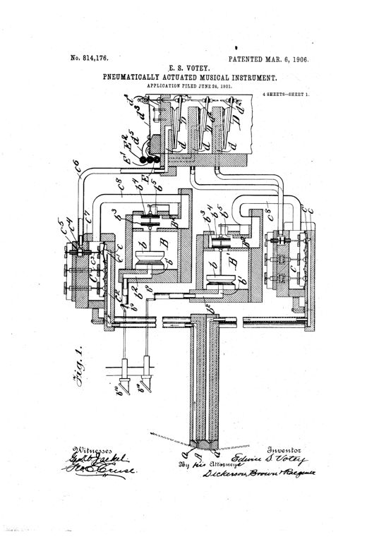
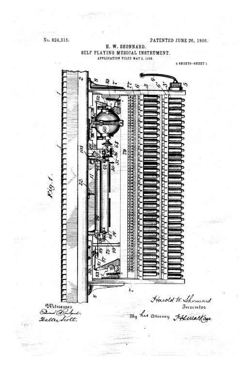
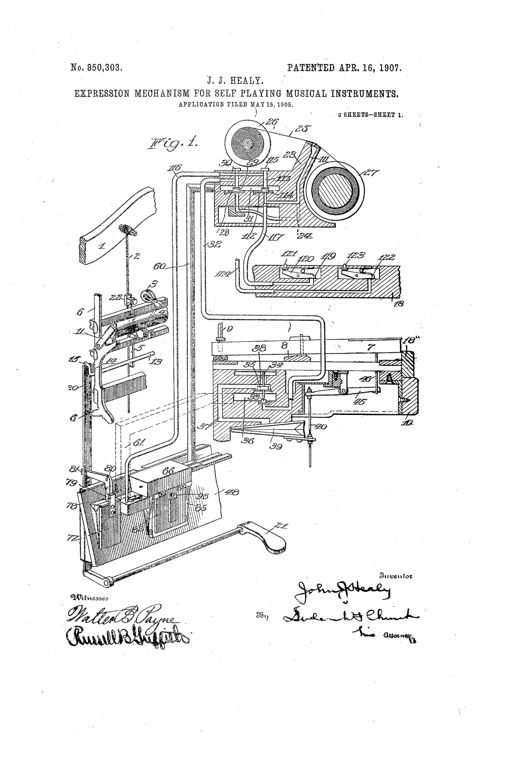
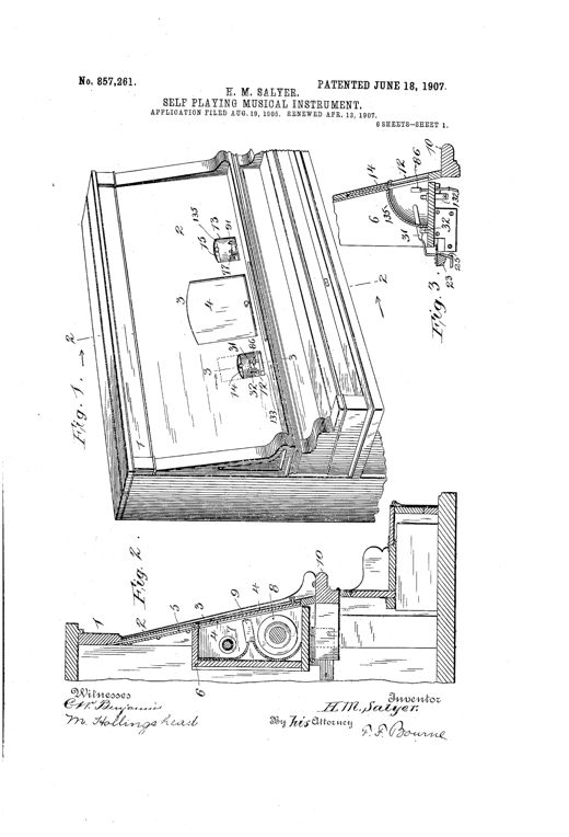
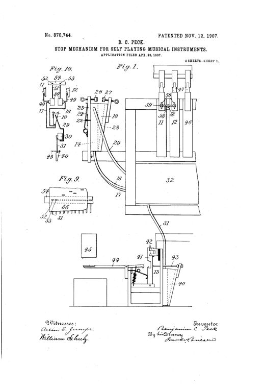
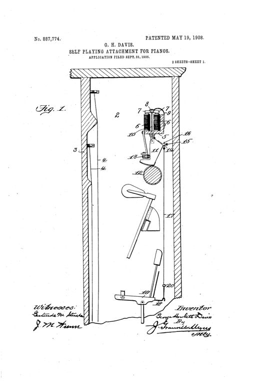
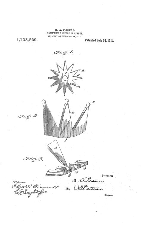
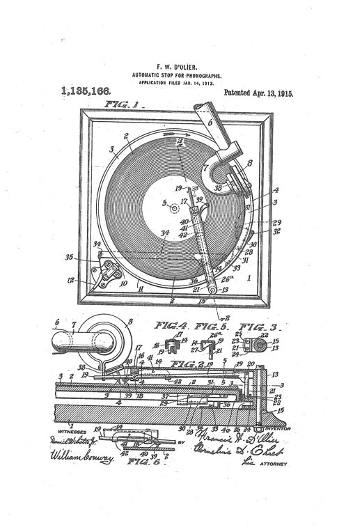
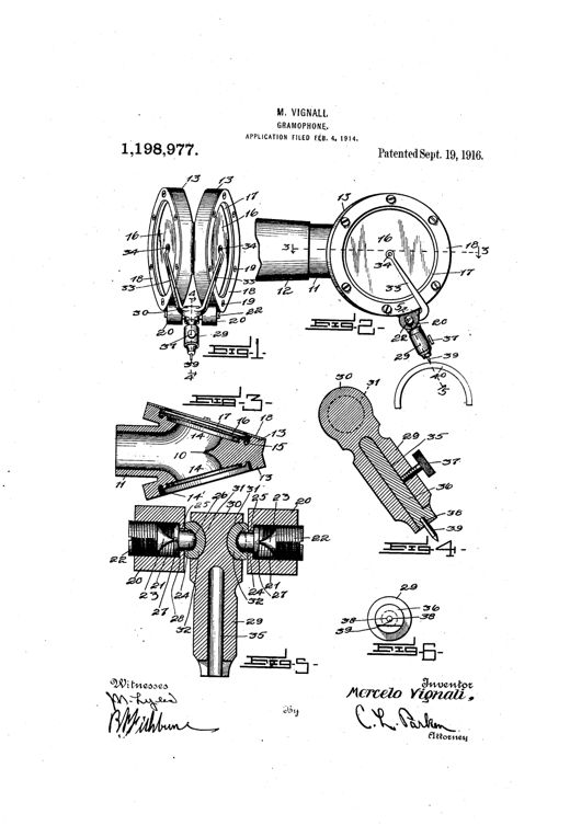
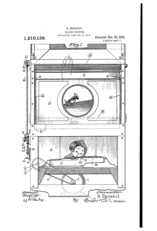
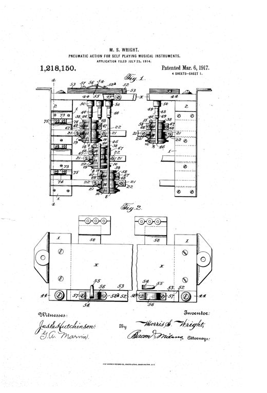
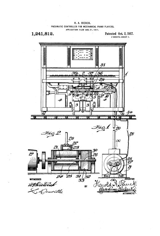
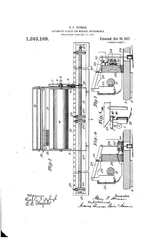
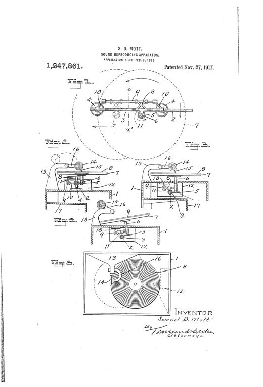
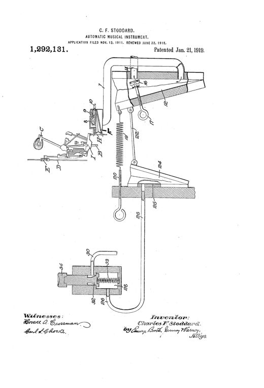
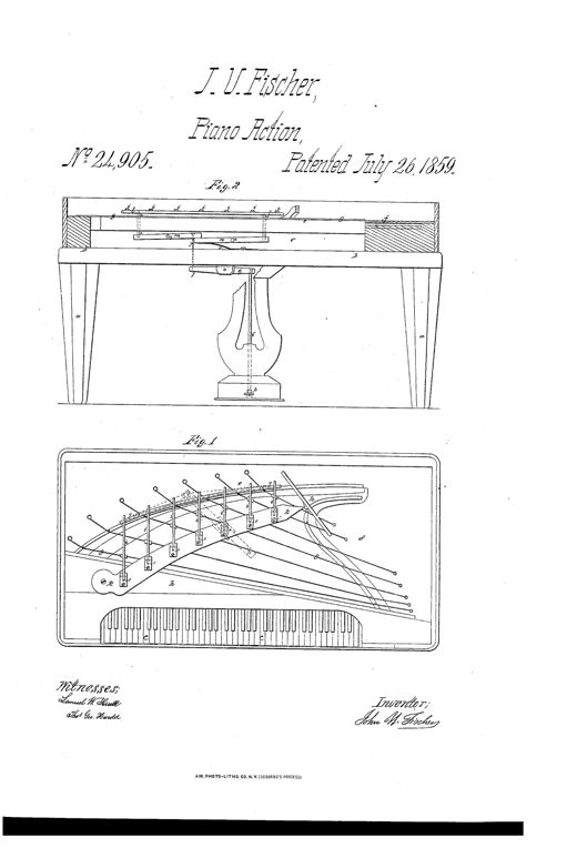
Patent drawing showing a piano case in cross-section elevation (Fig. 2) with legs, pedal rod, and lever mechanism beneath the rest plank, and a plan view (Fig. 1) of the piano's strings, dampers, and keyboard layout.PIANOFORTEJohn U. Fischer · July 26, 1859Patent drawing showing a rectangular music-board with rows of holes and movable type sliding beneath a keyboard of curved elastic levers connected by wires to electromagnets, with a side sectional view showing the type pins and lever mechanism.IMPROVEMENT IN ELECTRO-MAGNETIC MUSICAL INSTRUMENTSLorenzo Wesson · April 4, 1865Mechanical drawing of a Victorian musical instrument mechanism showing a plan view of an air chest with rows of pivoted finger-levers, valves, and rails (Fig. 1), and below it a side sectional view (Fig. 2) showing a perforated paper strip looping around two drum rollers connected by a belt-driven pulley system, with a diaphragm chamber and key linkage.IMPROVEMENT IN MUSICAL INSTRUMENTS.George W. Van Dusen · December 10, 1867Technical patent drawing of a multi-cylinder music box mechanism, showing a rectangular frame supporting several parallel cylinders mounted between two disks, with gear wheels, a hand crank, and a numbered dial plate indicating which cylinder is in play.IMPROVEMENT IN MUSICAL BOXESAmédeé Paillard · August 2, 1870Patent drawing of a cornet showing a coiled brass tube with a stationary casing housing a perforated revolving barrel above rows of keys, valves, and springs, with enlarged mechanical details of the ratchet, pawl, and stop-pin assembly in side figures.IMPROVEMENT IN MUSICAL INSTRUMENTS.Antonio L. Mora · July 23, 1872Two technical line drawings show a long cylindrical pattern-and-music cylinder assembly in cross-section (Fig. 1) with labeled holes and a boring tool, and a circular end-view cross-section (Fig. 2) revealing the nested pattern cylinder and inner music cylinder with aligned holes.IMPROVEMENT IN THE MANUFACTURE OF MUSIC-BOX CYLINDERS.Arnold Frankfeld · October 28, 1873An 1877 patent drawing showing a large coiled, printed music sheet feeding through a slotted guide into an angled reading apparatus with metal comb-mounted spring 'reader' fingers, gears, rollers, and multiple insulated wires leading off to electromagnetic actions housed in a wooden cabinet frame.IMPROVEMENT IN ELECTRO-PNEUMATIC MUSIC-PLAYING APPARATUS.William Ford Schmoele and Henry Schmoele, Jr. · April 10, 1877Patent drawing of an accordion-like automatic musical instrument showing a folding bellows chamber with a reed-board, a series of gears and ratchet wheels on a shaft, and below it a separate diagram of a long perforated valve-sheet strip marked with note letters and numbered apertures.IMPROVEMENT IN AUTOMATIC MUSICAL INSTRUMENTSHenry B. Horton · October 30, 1877Patent drawing of Edison's tinfoil phonograph showing a grooved cylinder flanked by two diaphragm assemblies with speaking tubes, connected via a threaded shaft and clockwork mechanism labeled with letters A through X.Improvement in Phonograph or Speaking MachinesThomas A. Edison · February 19, 1878Patent drawing showing the open wooden case of a mechanical musical instrument with paper-roll mechanism, geared rollers, and a sectional diagram of the pneumatic key and duct system with a large paper roll H.Mechanical Musical-Instrument.Merritt Gally · May 7, 1878Technical patent drawing showing a complex pneumatic player-piano mechanism with labeled keys, ducts, a large flywheel, crank handle, and perforated music-sheet chamber, alongside smaller detail figures of valve components.IMPROVEMENT IN MECHANICAL MUSICAL INSTRUMENTSMerritt Gally · November 26, 1878Exploded patent drawing of a cabinet-style reed organ labeled 'autophone,' showing a perforated paper valve-sheet feeding over rows of metal reed pipes, driven by a foot pedal, balance-wheel, and hand crank visible on the wooden case.Improvement in Mechanical Musical InstrumentsHenry B. Horton · December 3, 1878Patent drawing of a hand-held cylindrical music-making device labeled 'phuniphone,' shown gripped by a hand at a wooden handle, with internal bellows, reed plates, and paper rolls visible through the open casing.IMPROVEMENT IN MECHANICAL MUSICAL INSTRUMENTSMason J. Matthews · January 28, 1879Patent drawing showing four figures of a mechanical reed and pipe organ mechanism, including a wind-chest with a perforated paper roll traveling over an action-board with air passages leading to reeds and pipes, plus a plan view of the roll compartment with hinged lid and screws.IMPROVEMENT IN MECHANICAL MUSICAL INSTRUMENTS.Elias P. Needham · March 18, 1879Patent drawing of an upright organ or piano with an overhead frame holding a paper music-chart between two rollers, gears, and rows of pivoted false keys positioned above the instrument's keyboard.IMPROVEMENT IN SELF-PLAYING ATTACHMENTS FOR KEY-BOARD INSTRUMENTS.Edward Forbes O'Neill · May 6, 1879Patent drawing of a wooden orguinette-style mechanical organ mounted on a stand, showing two large paper-strip rollers at either end, a central reed box labeled with mechanism letters, a hand crank, and internal cross-section views of the bellows and shaft linkages.IMPROVEMENT IN MECHANICAL MUSICAL INSTRUMENTS.George B. Kelly and Mason J. Matthews · July 22, 1879Patent drawing of a tin-foil cylinder phonograph showing two geared cylinders, a central diaphragm with dual mouth-pieces and tubes, and a forked lever with recording points, alongside a side elevation of the full mechanism on its base.IMPROVEMENT IN PHONOGRAPHSA. Wilford Hall · September 23, 1879Patent drawing showing a mechanical reed organ with a treadle-driven fly-wheel shaft, bellows and wind-chest, and a perforated paper music-sheet passing over an action board between a music-roller and take-up roller, with detailed side and sectional views of the internal gearing and pawl mechanism.Mechanical Musical Instrument.Elias P. Needham · November 4, 1879Patent drawing of an Edison tin-foil cylinder phonograph showing a horizontal grooved cylinder mounted on a threaded shaft, flanked by supporting frames, a large flywheel and hand crank at one end, with a diaphragm and recording point assembly suspended beneath the cylinder; smaller inset figures show close-up views of the diaphragm holder, point mechanism, and a flexible speaking tube with mouthpiece.Phonograph.Thomas A. Edison · May 18, 1880Patent drawing showing a piano keyboard with an attached mechanical case containing a hand-cranked grooved roller, sliding jacks, and hammer-levers positioned to strike the keys via a perforated music-sheet.KEY-BOARD ATTACHMENT FOR MUSICAL INSTRUMENTS.Francis E. Moore · January 18, 1881Patent drawing of an electric music box showing a pinned cylinder, comb, gear train, and a U-shaped magnet armature motor mounted at one end, with a detailed mechanical linkage for a stop lever and friction spring at the opposite end.ELECTRIC MUSIC-BOX.Leonidas G. Woolley · February 1, 1881Patent drawing showing a plan view and cross-section of a mechanical reed organ with a perforated paper music-sheet running over rollers, a dome-shaped reed-board chamber, and bellows connected by cranks and pitmen.Mechanical Musical InstrumentMason J. Matthews · February 22, 1881Technical patent drawing of a musical box mechanism showing a geared cylinder, barrel, and time-wheel assembly in five labeled figures, with a signature reading Daniel Aubert at the bottom.MUSICAL BOX.Daniel Aubert · March 1, 1881Patent drawing of a mechanical organ showing a cabinet with bellows, a hinged reed-block with air chambers, and feed rollers guiding a perforated paper strip.Mechanical Musical Instrument.Oliver H. Arno · June 14, 1881Patent drawing of a reed-organ attachment showing a side-sectioned organ case with an internal wind chest, bellows, and treadle, alongside a compact perforated-paper-roll mechanism with music roller, take-up roller, and gear-driven roller assembly mounted atop the keyboard.MECHANICAL MUSICAL INSTRUMENT.Elias P. Needham and Charles A. Needham · July 26, 1881A cutaway perspective drawing of a small piano-shaped case showing a row of keys, a ratcheted roller, gears, and a music-box mechanism housed inside on curved cabriole legs.APPLICATION OF KEY-BOARD MECHANISM TO MUSIC-BOXESGeorge M. Patten · October 4, 1881Patent drawing of an automatic harmonica showing a reed-plate instrument mounted on legs, topped by a layered bellows and diaphragm assembly, with two side drums holding a perforated music sheet turned by crank handles.AUTOMATIC HARMONICA.Robert W. Pain · January 3, 1882Patent drawing of a cased mechanical reed organ showing an inclined reed-board, wind-chest, bellows arrangement, and paper music-roll transport mechanism with take-up roller and hand cranks, alongside detail views of the cover slats and roller construction.MECHANICAL MUSICAL INSTRUMENTAndrew H. Hammond · March 7, 1882Patent drawing of a cabinet-style mechanical reed organ showing internal rollers, a driving shaft with crank, bellows, and a wind-chest with valve mechanisms in cross-section and plan views.MECHANICAL MUSICAL INSTRUMENT.Andrew H. Hammond · March 7, 1882Patent drawing showing a cutaway mechanical musical instrument with a bellows, wind-chest, perforated music sheet feeding between rollers, and rows of organ pipes mounted above a movable sound-board.MECHANICAL MUSICAL INSTRUMENTHenry S. Taylor · June 6, 1882Patent drawing showing two long perforated paper music sheets with numbered rows of rectangular holes labeled 1 through 14 and a section view of a reed-board with a row of U-shaped reed chambers and reeds labeled c, d, f, and g.MECHANICAL MUSICAL INSTRUMENT.William A. Webber · July 18, 1882Patent drawing of an orguinette-style mechanical musical instrument showing the cabinet with music roller, take-up roller, reed-board with individual reed chambers, a detachable swell-box with slide-board and tremulant valve resting on the perforated music strip, and bellows with exhaust valves beneath.MECHANICAL MUSICAL INSTRUMENTJ. Herbert Chase · September 5, 1882Patent drawing of a cylinder musical box mechanism showing the pin-studded barrel, comb of tuned teeth, spring motor gearing, and a variable-toothed cog-plate tune-changer mounted on the end bearing block.MUSICAL BOX.Ernest Paillard · November 28, 1882A side-elevation patent drawing showing the internal mechanism of an automatic reed organ, with a bellows, reservoir bellows, reed pipes arranged in a fan pattern, a wound paper valve-sheet running over two rollers, and a hand-crank mechanism at top left.MECHANICAL MUSICAL INSTRUMENT.Henry B. Morris · December 12, 1882Patent drawing of a mechanical reed organ showing a vertical cross-section with bellows, reed-board, and paper-feed rollers, plus plan views of the perforated raceway and reed cells.MECHANICAL MUSICAL INSTRUMENT.Oliver H. Arno · December 26, 1882Technical patent drawing showing a boxed mechanism with a hand-cranked roller drawing a perforated paper sheet over rows of pivoted levers, connected via rods and elbow-levers to spring-loaded hammers that strike piano keys below.KEY-BOARD ATTACHMENT FOR MUSICAL INSTRUMENTSJoseph Schwertner · May 8, 1883Patent drawing of a wooden cabinet mechanical musical instrument showing a cross-section with bellows, reed cells, feed rollers, and a hinged air-chamber above a perforated music sheet rest, plus a plan view and an exploded perspective view of the same components.MECHANICAL MUSICAL INSTRUMENT.Edwin H. Brown · June 5, 1883Patent drawing of a small mechanical reed organ showing paper roll music sheet, bellows, a comb of short organ pipes, and a hinged compound reflector above the reed chest.MECHANICAL MUSICAL INSTRUMENTMerritt Gally · June 26, 1883Patent drawing of a mechanical harmonica with a hand-crank, geared rollers feeding a perforated paper band across a row of reed cells, plus detail views of the connecting card ends and a large disc-shaped roller assembly.MECHANICAL MUSICAL INSTRUMENT.Otto Zabekow · December 25, 1883Patent drawing of a McTammany automatic musical instrument case showing two large paper reels (M and N) connected by a belt and pulley system, with a central reed-board, feed rolls, pressure roll, and hand-crank drive mechanism visible in plan and sectional views.AUTOMATIC MUSICAL INSTRUMENT.John McTammany, Jr. · January 29, 1884Patent drawing of a mechanical musical instrument case with two perforated paper music sheets wound on rollers on either side of a central reed-board, connected to a hand crank, gears, bellows, and reversing levers.MECHANICAL MUSICAL INSTRUMENTGeorge H. Chinnock · May 6, 1884Patent drawing showing a piano's internal mechanism including key-levers, hammers, dampers, a large pin-barrel cylinder N with crank y, wind-chest H, small piston cylinders K, and connecting rods and levers labeled B through R, with inset figures 2 and 3 detailing the cylinder and piston arrangement.MECHANICAL MUSICAL INSTRUMENTCesare Donadoni · January 6, 1885Patent drawing showing a rectangular wooden frame housing a fan-shaped array of thin rod-like note-levers converging toward a central perforated music card mechanism, with rows of upright key-striking arms labeled G* extending outward, and control rods and gearing at the base of the frame.KEY-BOARD ATTACHMENT FOR MUSICAL INSTRUMENTS.Robert Hodges Bishop and William Down · February 10, 1885Patent drawing showing a cross-section of an organ pipe assembly with a tapered pipe (L), an air-passage and valve mechanism (D, A, B), an exhaust chamber, and a pneumatic linkage (P, N) connecting to a roller (N3), alongside two inset diagrams (Fig. 2) illustrating the flexible diaphragm and button construction.MECHANICAL MUSICAL INSTRUMENT.Merritt Gally · March 17, 1885Cross-sectional patent drawing of a music box showing an upright comb of tuned teeth, a pivoted picker-disk and lever mechanism, and a perforated metal sheet traveling along a bed plate driven by a pinion gear, with two additional perspective views of the sheet's projection pattern below.MECHANICAL MUSICAL INSTRUMENT.George B. Hakins · April 14, 1885Patent drawing of a McTammany automatic reed organ showing the internal gearing, bellows treadles, winding rolls, and a perforated music-sheet feeding over a reed-board inside a wooden case.MECHANICAL MUSICAL INSTRUMENT.John McTammany · July 7, 1885Patent drawing showing a hand-cranked mechanical musical instrument with a circular reed holder and handle in Fig. 1, its cross-section in Fig. 1A, and a rectangular two-row reed variant with scroll-decorated chest in Figs. 2 and 2A.MECHANICAL MUSICAL INSTRUMENTMarshall Arthur Wier · October 27, 1885Patent drawing of a trumpet-shaped mechanical musical instrument with internal reed scale-plate, rotating air tube, and perforated paper tune drum, shown in six labeled cross-sectional and end views.MECHANICAL MUSICAL INSTRUMENT.Marshall Arthur Wier · October 27, 1885Technical patent drawing showing a vertical cross-section of a phonograph sound reproducer: a wax-coated record disk (F) sits on a metal disk (E) mounted on an arbor (D), with a jet-tube (151) aimed at the record's surface and connected through a branching tube (154) to a diaphragm-equipped ear-piece (156), all mounted on an adjustable vertical standard (150).REPRODUCING SOUNDS FROM PHONOGRAPH RECORDS.Alexander Graham Bell, Chichester A. Bell, and Sumner Tainter · May 4, 1886Patent drawing showing a rotating wax-coated disk mounted on a base with an upright frame, a crank-driven flywheel turning the disk through gears, a cutting-style recorder mechanism above the disk connected by tubing to a nose-fitting mouth-piece, and several detail insets of the stylus, reproducer, and friction-clamp components.RECORDING AND REPRODUCING SPEECH AND OTHER SOUNDS.Chichester A. Bell and Sumner Tainter · May 4, 1886Patent drawing of an early wax-cylinder phonograph showing a large flywheel-driven cylinder mounted on a wooden base, with a recorder arm bearing a flaring elliptical mouth-piece and tapering tube feeding into a diaphragm and stylus assembly that traces the rotating tablet.APPARATUS FOR RECORDING AND REPRODUCING SOUNDSSumner Tainter · May 4, 1886Four patent drawings show a wooden box organette with a hand crank, an internal spindle and reed chambers, and a round perforated paper disc used to select the tune.AUTOMATIC MUSICAL INSTRUMENT.Ellis Parr · March 15, 1887A detailed engineering plan and side views of a wooden mechanical musical instrument case showing a perforated paper roll mechanism, crank handle, feed and presser rolls, paired bellows exhausters, and a reed-chest with individual reed cells, all labeled with reference letters for the patent drawing.MECHANICAL MUSICAL INSTRUMENT.J. Herbert Chase · March 29, 1887A patent drawing of a church-tower-shaped clock case with a steeple, a round clock face, and an internal pinned barrel mechanism connected by gears and levers to rows of bells at the base.MECHANICAL MUSICAL INSTRUMENT.Charles A. Kuster · May 24, 1887Patent drawing of a cabinet-style mechanical organ showing internal bellows, reed board, driving shaft with cranks, and paper music-sheet rollers, with a hinged cover above.MECHANICAL MUSICAL INSTRUMENT.J. Herbert Chase · May 24, 1887Patent drawing of a cylinder music box mechanism showing the pinned cylinder, tuned comb with teeth, main shaft with sleeves and sockets, and a separate cross-sectional detail of the locking sleeve and spindle assembly.MUSIC-BOXArthur Junod · July 12, 1887Patent drawing of a mechanical musical instrument showing a boxed frame with a perforated music-sheet stretched between two rollers, side gear wheels, a hand crank, and pivoted levers used to lift the take-up roller and stop the sheet's motion.MECHANICAL MUSICAL INSTRUMENT.James E. Treat · September 6, 1887Patent drawing showing a hand-cranked drum-shaped gramophone recording apparatus with a stylus arm, diaphragm, and support frame, along with detail views of the grooved record surface, a wavy recorded line, and a circular diaphragm assembly with labeled parts.GRAMOPHONEEmile Berliner · November 8, 1887Patent drawing of a cylinder music-box mechanism showing the pin-barrel, comb, mainspring casing, and a set of small pivoted plates with projecting points used to shift the barrel for different tunes.MUSIC-BOXLouis Campiche · December 6, 1887A hand-drawn patent illustration of a treadle-powered graphophone: an angled wooden frame supports a wax-tablet cylinder and gearing, with curved flexible speaking tubes ending in mouthpieces and an ear-trumpet horn arcing overhead, and a large foot-treadle wheel with spokes at the base of the machine.APPARATUS FOR RECORDING AND REPRODUCING SPEECH AND OTHER SOUNDSCharles Sumner Tainter · December 27, 1887Patent drawings depicting the internal mechanism of a Swiss cylinder music box, showing the pinned barrel, mainspring housing, tooth comb, driving-shaft disks, and a multi-faced cam plate used to shift the barrel and change tunes.MUSIC-BOXLouis Campiche · May 8, 1888Patent drawing of Edison's phonograph showing a circular electro-magnetic motor with four magnets and a fly-wheel, plus a horizontal cylinder machine with a horn, recorder and reproducer arms, and a swinging holder frame.PHONOGRAPH.Thomas A. Edison · July 31, 1888Patent drawing of a boxed phonograph recording apparatus showing a diaphragm and needle above a roller, flanked by two heating and cooling chambers with guide rollers, an oil lamp for heat, and gears and cranks (H, K, I) driving the recording strip through the mechanism.METHOD OF RECORDING SPEECH.George H. Herrington · November 13, 1888Patent drawing showing a horizontal shaft with a tapering hollow reamer, a large drive pulley labeled D, steam inlet and exhaust pipes, and a gage-arm mechanism, alongside a separate detailed cross-section and side view of the reamer's knife arrangement.MACHINE FOR MAKING PHONOGRAM-BLANKS.Thomas A. Edison · November 27, 1888Patent drawing showing five figures of a music box stop-motion mechanism with gear wheels, vertical shafts, a stop-lever, brake springs, and adjusting plates labeled with letters A through P.STOP-MOTION FOR MUSIC-BOXES.Gustave J. Jaccard · January 1, 1889Patent drawing of a hand-cranked toy phonograph mechanism showing a round sound head with funnel, a diaphragm reproducer riding on a threaded shell, a fly-wheel, and a crank handle, with a separate detail view of the spring-loaded tripping lever.PHONOGRAPH.Charles Batchelor · April 2, 1889Patent drawing of an ornamental cross-topped chime cabinet with internal clockwork, bells, and a rotating perforated paper mechanism that controls electro-magnetic hammers striking a series of bells.MECHANICAL MUSICAL INSTRUMENT.Willard H. Gilman · May 21, 1889Patent drawing of a graphophone recording apparatus showing a frame with gears, a screw-threaded shaft, a record cylinder mounted between standards, a recorder with flexible speaking tube and diaphragm, and a separate bench-mounted machine with a rotating cylinder and adjustable weighted arm for smoothing the wax surface.METHOD OF REPREPARING GRAPHOPHONE-TABLETS.David Wolfe Brown · August 6, 1889Patent drawing showing a four-lobed clover-shaped apparatus with resonant chambers (Fig.1), a sectional view revealing an internal spider-arm mechanism converging to a central stylus point connected to a flaring horn-like tube (Fig.2), and detail views of the diaphragm plates, tensioning pin, and record-making point/wheel (Figs.3-5).APPARATUS FOR THE RECORD AND REPRODUCTION OF SOUNDS.Gianni Bettini · August 13, 1889Patent drawing of a small mechanical toy phonograph showing a spherical resonator atop a cylindrical mechanism with diaphragm, stylus, gears, and a coiled spring assembly, illustrated in four labeled figures.PHONOGRAPH.William W. Jacques · October 22, 1889Patent drawing showing a circular fan-folded music sheet made of overlapping sectors mounted in a mechanical instrument box, with detail views of the roller feed mechanism, connecting tappets, and sliding sector joints.MUSIC-SHEET FOR MECHANICAL MUSICAL INSTRUMENTS.Friedrich Ernst Paul Ehrlich · April 15, 1890Patent drawing of an early gramophone reproducer showing a large conical horn mounted on a pivoted arm with a counterweight rod, connected to a diaphragm and stylus resting on a flat rotating record disk driven by a hand crank.GRAMOPHONE.Werner Suess · May 6, 1890Mechanical drawing of an Edison phonograph attachment showing a spectacle-frame arm with a threaded presser-foot bar, a pivoted determining-point lever, and a locking mechanism positioned above a cylindrical phonogram-blank labeled U.AUTOMATIC DETERMINING DEVICE FOR PHONOGRAPHS.Thomas A. Edison · June 17, 1890Patent drawing of a graphophone showing a horizontal record cylinder beneath a hinged diaphragm-frame carrying a recording style, with a separate speaking-tube support and a swinging reproducer arm mounted on a sliding carriage along guide rods.GRAPHOPHONEJohn H. White · July 15, 1890Patent drawing showing a rectangular wooden frame with inclined side standards holding two parallel rollers wrapped in an endless knobbed belt, a hand crank and pulley system on one end, and a row of spring tappet-levers beneath the rollers aligned over piano keys.KEY-BOARD ATTACHMENT FOR PIANOSCasper De Vilbiss · August 12, 1890Patent drawing of a cylinder phonograph with a reproducing carriage on a threaded shaft, a curved flexible tube leading to an external funnel, and mechanical levers and rails for automatically lifting and returning the carriage.AUTOMATIC REPEATING MECHANISM FOR PHONOGRAPHS.Jacob H. Ling · November 4, 1890A cutaway side-elevation engineering drawing of a Victorian tabletop cylinder phonograph, showing a conical listening horn, a threaded rotating cylinder holding a tubular tablet, a governor bellows and friction gearing beneath, and a detachable water-filled heating tank slid along guide rails at the front.PHONOGRAPH.Isaac W. Heysinger · November 11, 1890Patent drawing of a cylinder phonograph showing the main frame with grooved record cylinder, a diaphragm and pivoted style assembly on a sliding carriage, a large curved amplifying horn rising above, and several detail cross-sections of the reproducer mechanism below.PHONOGRAPH.John H. White · November 11, 1890Patent drawing of a graphophone erasing attachment showing a record cylinder, carriage with reproducer and recorder arms, and a hinged eraser roller mechanism with control rods and finger-piece, plus enlarged detail views of the eraser wheel and alternate blade forms.ERASING ATTACHMENT FOR PHONOGRAPHS.Philip T. Dodge · March 31, 1891Technical patent drawing showing a mechanical phonograph with two reels (B and B') connected by a wax-coated ribbon (D) that passes over a guide roller (C), with a hinged cover housing an adjustable diaphragm and stylus assembly, plus detailed cross-sections of the reel and roller mechanism.PHONOGRAPH.Eustace Oxley · September 1, 1891Patent drawing of a cylinder phonograph mechanism showing the recording cylinder, diaphragm arm, lifting-bar with cam-disk, and a pivoted lever labeled 'prime mover' used to start the motor and raise or lower the stylus.PHONOGRAPH.Henry T. Holtz · November 24, 1891Patent drawing showing a boxed phonograph apparatus with a diaphragm and needle above a central roller, flanked by heating and cooling chambers labeled E and F containing a recording strip guided by pulleys and rollers, with gears and a motor below, plus a separate figure of a cylindrical phonograph with a lamp for heating the recording sheet.PHONOGRAPH.George H. Herrington · December 1, 1891Patent drawing of an Edison cylinder phonograph showing the mandrel, cylinder-shaft with feed-screw, rocking holding-arm with combined recorder and reproducer, hand crank, and separate detailed views of a flared mouth-tube and an ear-tube attachment.PHONOGRAPH.Thomas A. Edison · December 29, 1891Patent drawing of a graphophone mechanism showing a wax cylinder, a curved sound tube leading to a horn, a diaphragm-supporting frame with pivoted styles, and a threaded guide rod for traversing the cylinder, with hand-signed inventor and witness signatures below.PHONOGRAPH.John H. White · January 26, 1892Patent drawing of a cylinder phonograph mechanism with a screw-threaded shaft, spring, cam, and latch assembly, shown both as isolated hardware and mounted inside the hollow body of a crow figure on a pedestal.PHONOGRAPH.Francis M. Criswell · March 8, 1892Patent drawing of a conical phonograph horn with an internal cone-shaped deflector, concave annular and spherical reflectors, a diaphragm, and an electrically heated recording stylus mounted on springs and insulating mica strips.APPARATUS FOR RECORDING SPEECH OR OTHER SOUNDSWilliam Bruening · November 15, 1892Two vertical sectional diagrams of a phonograph recording apparatus showing a corrugated horn, a cone-shaped diaphragm with a stylus, a dome-shaped sound reflector, and a small lamp used to heat the stylus, with labeled parts including horn (H), diaphragm (D'), cone (C), style (S), and support stem (M).APPARATUS FOR RECORDING SPEECH OR OTHER SOUNDSWilliam Bruening · November 22, 1892Patent drawing showing a phonograph with a large horizontal phonogram cylinder, an angled diaphragm assembly with a mouthpiece and thumb-nut adjustable arm above, and a weighted stylus support mechanism below, with labeled parts including the cylinder axis A, diaphragm ring N, and shield J.PHONOGRAPH.Gianni Bettini · December 20, 1892Patent drawing of a Bettini phonograph showing a cylindrical mandrel labeled A and C beneath an angled tone-arm assembly with mouthpiece M, diaphragm ring N, and spider S holding two styluses, with a small dual-faced weight indicator labeled 'Recording' and 'Reproducing' shown separately above.PHONOGRAPH.Gianni Bettini · December 20, 1892Patent drawing of a mechanical musical instrument showing a box with a perforated paper roll fed over rows of spring-loaded hammers that strike tuned metal tongues, with cross-section and detail views of the hammer and damper mechanism in various positions.MECHANICAL MUSICAL INSTRUMENT.Theodor Zöllner · April 4, 1893Patent drawing showing an Edison phonograph mechanism with a cloth-wrapped speaking horn, a coiled wire leading to a circuit controller plug, a cylindrical mandrel labeled 1, a rocking holding arm numbered 2, an electro-magnet and tilting bar assembly with armature 17, and a separate diagram of the recorder/reproducer plate with cam and pivot mechanisms labeled 20 through 30.PHONOGRAPHThomas A. Edison · April 25, 1893Patent drawing of a rectangular wooden frame mounted atop a piano keyboard, showing rows of pivoted hammers, a perforated paper music sheet threaded over rollers at top and bottom, and a hand crank with gears driving the sheet across the hammer tips.ATTACHMENT FOR MUSICAL INSTRUMENTS.George Brown · February 6, 1894Patent drawing of a chime-ringing apparatus showing four bells mounted in a frame with hammers and dampers, a rotating shaft with friction pulleys and electro-magnets below, and a keyboard with battery cells connected by wires to operate each bell's hammer.CHIME-RINGING MECHANISM.William C. Wilkins · March 13, 1894Patent drawing of a rectangular case fitted over a piano or organ keyboard, showing internal rollers, a crank wheel, a perforated metal sheet feeding through gears, and rows of pins aligned with keys.AUTOMATIC ORGAN-PLAYER.John August Brodin · July 31, 1894Patent drawing of a mechanical music player showing a paper roll feeding over a star wheel with plungers, geared to a spring-driven blade cylinder that plucks a comb.AUTOMATIC MUSICAL INSTRUMENT.William H. Hoschke · December 18, 1894A multi-view mechanical patent drawing showing a wooden case with levers, rods, and a perforated paper card threading through a keyboard-actuating mechanism mounted atop an organ's keys.MECHANISM FOR ACTUATING KEYBOARDS BY MEANS OF PERFORATED CARDSClaude Gavioli · December 25, 1894Patent drawing of a phonograph mechanism showing a horn-shaped diaphragm chamber connected via U-shaped amplificatory levers and a rocking bar to interchangeable recording and reproducing styles, with detailed close-ups of the lever linkage and style shanks.PHONOGRAPHStewart Dixon McKelvey · January 1, 1895Patent drawing of a mechanical musical instrument showing a comb-and-pin-wheel mechanism, a rotary disk carrying a perforated music sheet with concentric slot tracks, a cam and spring-loaded sliding block for shifting the sheet's center, and a spur wheel and shaft assembly for rotating the sheet.MECHANICAL MUSICAL INSTRUMENT.Max Hauschild · January 1, 1895Technical patent drawing showing four side-elevation views (Figs. 1-4) of a small pivoted hammer mechanism with labeled parts a, b, c, d, e, f, g, h interacting with a perforated note sheet and a steel tongue above a hatched base plate, plus a fifth isolated detail view of the hammer (Fig. 5).DEVICE FOR VIBRATING TONGUES OF MUSIC-BOXESAdolf Richter · January 15, 1895A perspective mechanical drawing of an early disc gramophone recorder showing a flat horizontal disc mounted on an upright shaft, a hand crank and flywheel driving the mechanism via gears and a screw-threaded shaft, a diaphragm and stylus assembly on an arm above the disc, and a flexible tube leading to a flaring alcohol reservoir and a curved sound-conveying tube ending in a bell-shaped mouth-piece.GRAMOPHONE.Emile Berliner · February 19, 1895Patent drawing showing side and top views of a music-box damping mechanism with a pivoted damper plate, pin cylinder, vibrating tongue, and adjustable support plate, labeled with reference letters a through z.DAMPING MECHANISM FOR MUSIC-BOXES.Ami Constant Jaccard · April 2, 1895Patent drawing of a disc musical box mechanism showing a large perforated note disc, gear train, spring drum, governor fan, and comb assembly with labeled parts A through W.MUSICAL BOX.Ferdinand Schaub · April 30, 1895Front elevation of an upright piano case with three paneled windows above the keyboard, a small pointer and dial labeled O and P near the treble end of the keys, three pedals below, and accompanying schematic diagrams of the electric circuit, perforated control strip, and circuit-closer mechanism beneath the main drawing.EXPRESSION-INDICATOR FOR SELF-PLAYING INSTRUMENTSFrederick W. Hedgeland · November 19, 1895Patent drawing with five figures: Fig.1 shows a side view of a recording apparatus with a round diaphragm A atop a rim B, a bifurcated stylus C reaching down to a moving paper fillet R threaded between rollers D and D', and a small liquid reservoir S feeding a capillary tube; Fig.2 is a face view of the same diaphragm A with an induction coil T, battery terminals P and P', and the fillet R passing between two circular rollers; Fig.3 shows a rear view of gear-like rollers E, E1, E3 and E4 engaging the narrower fillet strip r; Fig.4 is a tall vertical cross-section of a cylindrical apparatus with an inner glass cylinder L suspended by a cord over pulleys O to a weight W, dipping into a liquid-filled outer vessel K containing liquid M, with a diaphragm L at the top connected to tubes i and J; Fig.5 is a small detail showing two crossed wires labeled c and c2 forming an X shape on the fillet R.ART OF RECORDING AND REPRODUCING IMPULSES.William H. Cooley · December 24, 1895Technical patent drawing showing a music box mechanism with a sectional elevation (Fig. 1) of reeds, toothed striker-wheels, and a note-sheet on rollers, plus two detailed plan views (Figs. 2 and 3) of rows of reeds with adjustable striker mechanisms, and small detail views (Figs. 4 and 5) of the toothed actuating and striker wheels.MUSIC-BOX.Paul Th. A. Rodeck · May 5, 1896Technical patent drawing showing a mechanical music player's feed wheels, perforated music sheet with driving holes, fly-wheel governor mechanism, and a cabinet console housing the instrument.AUTOMATIC MUSICAL INSTRUMENT.Adolf Richter · May 19, 1896Patent drawing showing a row of vertical metal tongues mounted above a toothed pick wheel assembly, with detail views of the divided spur-wheel teeth engaging a perforated paper music sheet.SPUR-WHEEL FOR MUSICAL INSTRUMENTS.Paul B. Th. Berner · September 22, 1896Patent drawing of a chiming mechanism showing a large pinned cylinder barrel, hammer shanks striking tubular bells, gearing, a fan regulator, and a start/stop control panel with numbered tune-selection holes.CHIMING MECHANISM.Allan E. Olney · November 10, 1896Patent drawing showing a spring-metal damper arm pressing against a toothed star-wheel that vibrates a metal music-tongue, with several detail views of the forked damper blank and its bent damping-finger.DAMPING DEVICE FOR MECHANICAL MUSICAL INSTRUMENTS.Friedrich Adolf Richter · April 20, 1897Patent drawing of a rectangular musical instrument case showing rows of tuned strings, a pinned rotating cylinder, gear train, hammer-carriage with individual hammers, and a hand crank winding lever, all mounted on a wooden base-block.MECHANICAL MUSICAL INSTRUMENT.Louis Stocker · September 28, 1897Patent drawing of a music box cabinet showing the comb and star-wheel mechanism, cylinder, battery, induction coil, and wired handles for administering electric shocks in time with the music.ELECTRICAL MUSICAL INSTRUMENT.Gustav A. Brachhausen · December 21, 1897Cutaway front elevation of an upright piano cabinet revealing the pneumatic player mechanism, including vertical striking bellows, valve-board, tubing to a tracker bar, paired music rolls in a lower drawer, and a flywheel-driven exhaust pump at the base.AUTOPNEUMATIC PIANO-PLAYERFred R. Goolman · February 1, 1898Patent drawing showing a piano attachment with a battery, electric motor, rotating friction drums, a bank of electromagnets with striker rods, a perforated paper music roll and take-up spool, and a sliding drawer contact mechanism, with the inventor's cursive signature at bottom.ELECTROMECHANICAL MUSICAL INSTRUMENT.George Howlett Davis · June 28, 1898Patent drawing of a cylinder phonograph reproducer assembly showing the mouthpiece, diaphragm ring, spring-arms, universal joint pivot, and stylus arranged over a record cylinder, with additional detail views of the yoke, pin, and spring connections.DEVICE FOR REPRODUCING SOUNDHenry J. Hagen · November 15, 1898Cutaway perspective drawing of a piano corner exposing internal gears, pulleys, belts, a motor, and an electric switch mechanism beneath the keyboard and leg.ELECTRIC PIANOGeorge Schrade and Harold W. Shonnard · May 2, 1899Technical patent drawing showing a phonograph diaphragm assembly in cross-section and face view, with a stylus bar D extending downward through a yielding spring plate E to a needle point d', alongside detail views of grooved supporting plates labeled Fig. 5, 6, and 7.SOUND RECORDING AND REPRODUCING MACHINEAlfred Corning Clark and Eldridge R. Johnson · May 9, 1899An ornate open music box with a mirrored lid, showing the comb mechanism and rotating disk inside, alongside cross-section diagrams of the sounding-board, resonance boxes, and a hand-crank cithern attachment mechanism.MUSIC-BOX.Levi D. Markle · May 16, 1899Patent drawing showing four side-view diagrams of a toothed tripping wheel mounted on an eccentric pivoted disk beneath a perforated music sheet, with a fifth detail figure of the frame's circular support opening.DEVICE FOR TRIPPING VIBRATING TONGUES OF MECHANICAL MUSIC-BOXESAndré Junod · July 18, 1899Patent drawing sheet showing six figures of a small toy phonograph: a side view and end view of the whole machine on a base with cylinder and crank, an enlarged cross-section of the sound tube chamber, two comparative details of the diaphragm and double-pointed pin in reproducing versus recording positions, and an isolated view of the bifurcated diaphragm pin itself.TOY PHONOGRAPH.Jean Schoenner · August 8, 1899Patent drawing showing a piano casing labeled A next to an automatic playing device labeled B, with a detailed pedal-linkage mechanism including a shaft, collars, spring, and pedal C illustrated in four separate figures.PEDAL ATTACHMENT FOR AUTOMATIC PLAYING DEVICES.Robert W. Pain · August 8, 1899Patent drawing of a self-playing piano attachment showing a row of vertical key-levers with pneumatic bellows, an exhaust trunk system, and a tracker-board with radiating air-ducts, alongside a side-sectional view of the case with bellows, treadles, and adjustable key-lever bar.SELF-PLAYING ATTACHMENT FOR MUSICAL INSTRUMENTSTheodore Parker Brown · October 17, 1899Patent drawing showing three views of a graphophone reproducer-lifting mechanism, including the carriage, pivoted neck, reproducer-head with soundbox, and a cam-actuated stop-ring and plunger assembly labeled with reference letters A through K.LIFTING MECHANISM FOR GRAPHOPHONE-REPRODUCERS.Thomas H. Macdonald · November 14, 1899Mechanical drawing of a patent showing a spool-fed perforated paper pattern engaging a toothed carrier gear that drives a cylinder studded with spring-loaded dogs, which strike a row of pivoted levers connected to piano keys, with detail insets of the fixed hub, cam, dog, ring, jack, and a section of the punched pattern sheet.PATTERN-OPERATED MECHANICAL MOVEMENTMartin E. Greenhouse · December 5, 1899A detailed mechanical patent drawing showing a long rectangular casing mounted over a piano keyboard, containing rows of numbered valves, plungers, rollers, cog-wheels, and a governor mechanism connected by tubing to an external air compressor and tank.SELF PLAYING ATTACHMENT FOR KEY MUSICAL INSTRUMENTS.Harry M. Salyer · July 10, 1900Patent drawing of a round rotating note-sheet mechanism mounted on a long banjo-like body, showing radial star-wheels, bridges, fret bars, and a hand crank used to automatically pluck and finger strings.SELF-PLAYING STRINGED MUSICAL INSTRUMENTFriedrich Schneider · February 26, 1901Cutaway mechanical drawing of a player-piano pneumatic mechanism showing the vacuum chamber, key-pneumatics, tracker board with a perforated paper music roll passing over it, feeder bellows, and pedal linkage, alongside detail views of the tracker board slots and a music-sheet with rows of numbered perforations.AUTOMATIC PIANO-PLAYERErnest M. Skinner · May 7, 1901Patent drawing showing a rectangular attachment frame mounted diagonally over the strings of a cithern, with labeled side strips, cross-bars, a hand crank, feed wheels, and rows of picker-levers extending down between the strings, alongside detail views of the perforated music sheet and lever mechanism.SELF PLAYING STRINGED MUSICAL INSTRUMENTJoseph Panholzer · May 28, 1901Patent drawing showing a boxed pneumatic mechanism with bellows chambers, diaphragms, valve spindles, and a lever rod connected to a piano key, alongside a wheel-driven motor variant for advancing the music roll.MECHANICAL PIANO-PLAYERCharles L. Davis · June 11, 1901Patent drawing showing a piano's interior with rock-shafts, hand levers, telescoping vertical bars, springs, and pedal-depressing arms mechanically linked to depress the piano pedals.PEDAL-OPERATING MECHANISM FOR AUTOMATICALLY-OPERATED MUSICAL INSTRUMENTSTheodore Parker Brown · December 3, 1901Cutaway side-view engineering drawing of an upright piano-player cabinet showing the adjustable finger mechanism, guide rods, standards, tracker bar, bellows chest, and pedal-driven pump linkage inside the case.AUTOMATIC PIANO-PLAYERFrank C. White · April 8, 1902Cross-sectional mechanical drawing of an automatic banjo-playing device showing a circular banjo head surrounded by valve casings, tubing, pickers, and fret-actuating fingers connected to pneumatic bellows.AUTOMATIC STRINGED MUSICAL INSTRUMENTFrederich W. Wood and Edward H. Stiles, Jr. · June 17, 1902Patent drawing of an upright piano with a separate adjacent cabinet housing the pneumatic tracker-board and paper roll mechanism, with detailed cross-section views of the internal pneumatic bellows and key-lever linkages.AUTOMATIC PLAYING ATTACHMENT FOR MUSICAL INSTRUMENTS.Theodore P. Brown · March 31, 1903Patent drawing of a player-piano cabinet's internal pneumatic mechanism, showing tracker board, choker valve boxes, operating pneumatics, and pedal-actuating rods, with detail insets of the choker valve and control lever assembly.ACCENTUATION MECHANISM FOR AUTOPNEUMATIC MUSIC-PLAYING INSTRUMENTS.Nelson D. Hosley and Stillwell R. Harcourt · August 18, 1903Patent drawing of a player-piano expression-control attachment showing a gated box with multiple air passages, a pivoting operating handle with a dynamics scale from pianissimo to fortissimo, and linked rods and springs connecting to a supplemental valve.ATTACHMENT FOR EXPRESSION OR ACCENT CONTROLLING MECHANISMS FOR MECHANICAL MUSICAL INSTRUMENTS.Robert W. Pain · February 23, 1904Patent drawing of a player-piano mechanism showing a paper music roll, tracker board, divided wind-chest with valve casings, and two pivoted hand levers positioned near an indicating scale for controlling bass and treble tension independently.MEANS FOR CONTROLLING THE TENSION IN WIND WAYS OF MECHANICAL-MUSICAL-INSTRUMENT PLAYERSJoseph H. Dickinson · January 17, 1905Patent drawing showing a player-organ mechanism with a tracker-board, rows of pneumatic bellows, exhaust chests, wind ducts, and electromagnetic switch contacts connecting to organ pipes.PNEUMATICALLY-ACTUATED MUSICAL INSTRUMENTEdwin S. Votey · March 6, 1906Front elevation of a piano's interior mechanism showing rows of cylindrical electromagnets, transmission rods, and a perforated paper roll assembly mounted beneath an open keyboard, with a small electric motor and driving wheel at upper right.SELF-PLAYING MUSICAL INSTRUMENT.Harold W. Shonnard · June 26, 1906Exploded mechanical drawing of a player-piano expression mechanism showing a paper music roll feeding over a tracker-board connected via tubing to a bank of pneumatic bellows, valves, and levers that operate the piano's hammer-rail and damper system, with a foot-pedal lever at the bottom.EXPRESSION MECHANISM FOR SELF-PLAYING MUSICAL INSTRUMENTS.John J. Healy · April 16, 1907An exploded perspective drawing of the upper interior of a player piano, showing the sliding door and roll receptacle above the keyboard, rows of numbered pneumatic bellows and wippen-engaging arms, and a side detail of the governor and valve assembly for the paper-roll drive motor.SELF-PLAYING MUSICAL INSTRUMENT.Harry M. Salyer · June 18, 1907Patent drawing showing a front elevation of a player-piano stop mechanism with labeled bellows, ducts, valves, and switch components mounted on a wooden frame, alongside detail figures of the auxiliary bellows and duct-bridge.STOP MECHANISM FOR SELF-PLAYING MUSICAL INSTRUMENTS.Benjamin C. Peck · November 12, 1907Patent drawing of a piano's upper casing showing a self-playing mechanism with paired electromagnets, a rocking armature, a shoe pressing against a spinning roller, and a tape running down to the piano's hammer action and keys.SELF-PLAYING ATTACHMENT FOR PIANOS.George Howlett Davis · May 19, 1908A patent drawing showing a twelve-pointed star-shaped gramophone needle with a central hole, an enlarged view of three of its tapering points ending in rounded elliptical tips, and a cross-section of one point seated in a record's sound groove.GRAMOPHONE NEEDLE OR STYLUSMinard A. Possons · July 14, 1914Patent drawing of a disc phonograph top plan view showing the tone arm, horn, sound box with stylus riding on a spiral-grooved record, and an automatic stop mechanism with a pivoted arm, rod, and brake linkage mounted near the platen edge, with additional detail views of the brake components below.AUTOMATIC STOP FOR PHONOGRAPHS.Francis W. D'Olier · April 13, 1915Patent drawing of a gramophone sound box showing two angled diaphragm rings connected by pivoting arms to a needle-carrying lever, with detail views of the pivot studs, elastic pads, and needle clamp.GRAMOPHONE.Marcelo Vignali · September 19, 1916Front elevation of a tall cabinet-style talking machine housing an advertising sign window above a phonograph mechanism with gears, feed screw, and cylinder record visible below.TALKING-MACHINEBernard Benedict · December 26, 1916Technical patent drawings of a player-piano pneumatic action showing stacked metal headers, valve casings with numbered valve disks and rods, a vacuum chamber casing, and a hinged motor pneumatic with a striker bar bracket, along with detail views of individual valve components and wedge blocks.PNEUMATIC ACTION FOR SELF PLAYING MUSICAL INSTRUMENTSMorris S. Wright · March 6, 1917Patent drawing of an upright player piano cabinet with exposed pneumatic mechanism including foot treadles, air reservoirs, valve conduits, and a motor-driven blower assembly connected beneath the floor.PNEUMATIC CONTROLLER FOR MECHANICAL PIANO-PLAYERSHarold A. Bierck · October 2, 1917Patent drawing of an electromagnetic player-piano mechanism showing a rotating shaft, rows of magnets on pivoted walking beams, a tracker bar with a bristle brush contacting a perforated paper music roll, and thrust rods connecting to the piano keys.AUTOMATIC PLAYER FOR MUSICAL INSTRUMENTSHenry F. Herman · October 16, 1917Patent drawing showing a phonograph mechanism with a screw-driven shaft, pinion, and toothed rack that rotates and bodily moves a turntable holding a spiral-grooved record disk beneath a fixed reproducer arm and stylus, illustrated across five figures including plan views, side cross-sections, and a top-down view of the record and tone arm assembly.SOUND-REPRODUCING APPARATUSSamuel D. Mott · November 27, 1917A technical line drawing of a player-piano mechanism showing a hammer-and-key action linked by rods and springs to a horn-shaped pneumatic bellows, a coil spring, a secondary tilted pneumatic labeled 24, and a small valve cylinder with a manual button labeled 34 at the bottom, all connected by numbered ducts and levers.AUTOMATIC MUSICAL INSTRUMENTCharles F. Stoddard · January 21, 1919