PHONOGRAPH.
Feeding sound to the diaphragm's underside so loud passages dig in, not skip
Improved recording/reproducing mechanism for a graphophone
♫ How it works
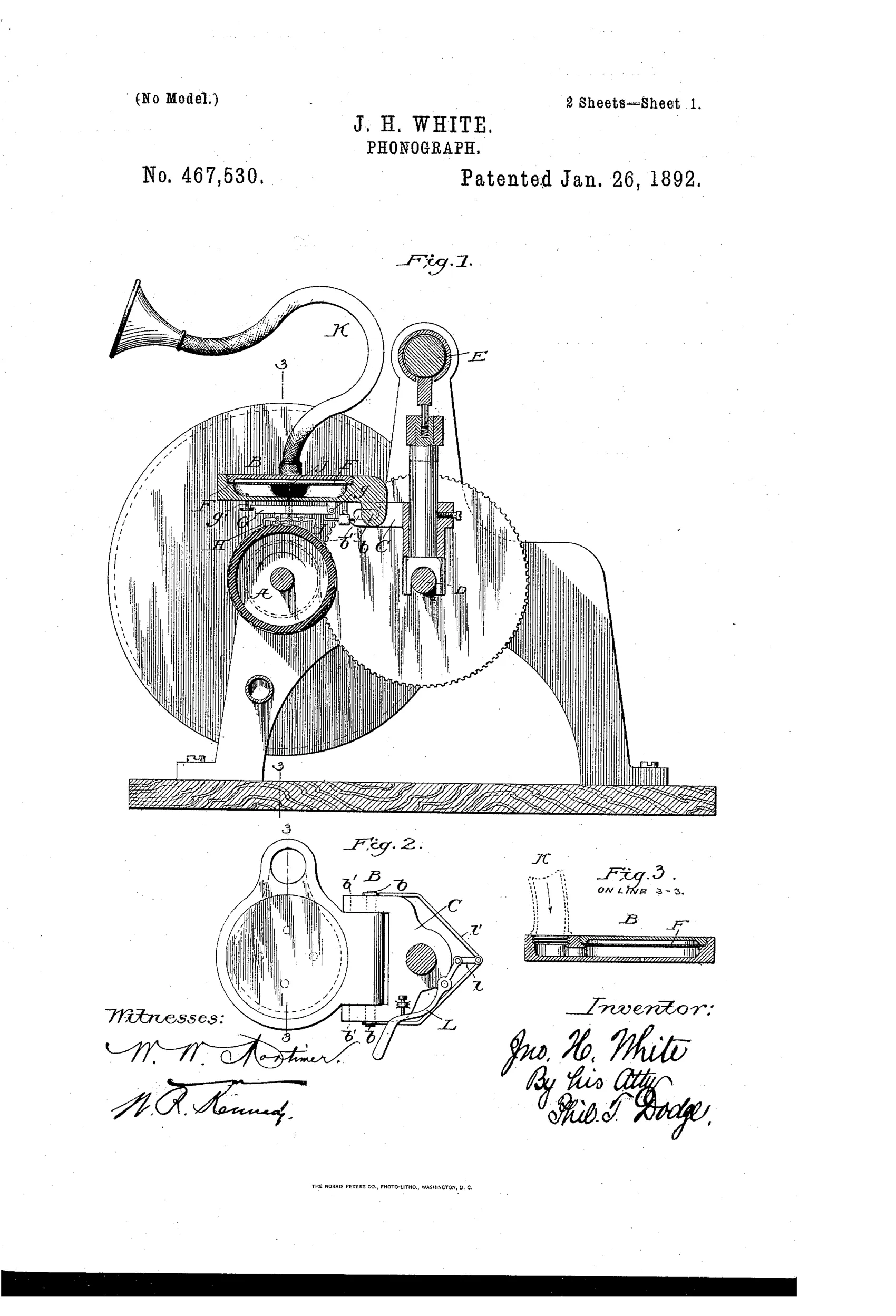
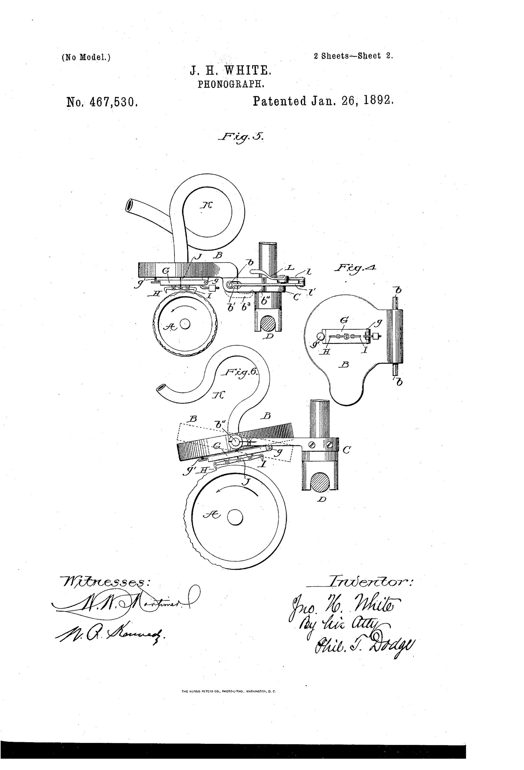
Sound waves strike the underside of the diaphragm through a chamber fed by a sound tube, lifting the diaphragm rather than depressing it, which pulls upward on the heel end of the recording style via a thread connection. This upward pull opposes the downward gravity-driven pressure of the style-supporting arm, using the arm's weight and inertia to keep the style properly engaged with the wax cylinder even during loud sound bursts. A separate reproducing style, jointed end-to-end with the recording style in the same vertical plane, shares the diaphragm connection and can be swapped into operative position by sliding or rocking the diaphragm-supporting frame on its carriage. The carriage travels along a guide parallel to the record-cylinder via a feed screw, advancing the styles across the wax-coated cylinder as it revolves.
♫ What was claimed
“1. In a sound-recording mechanism and in combination with a record-receiving body, a pivoted style acting on the record-body, a yielding style-supporting arm tending to move the style toward the record-surface, a diaphragm connected to the style, and means for directing the sound waves or impulses against the diaphragm in such direction that it tends to urge the style toward the record in opposition to the tendency of the yielding arm.”
In plain English: A recording mechanism where sound waves push the diaphragm in a direction that forces the recording stylus into the wax cylinder, counteracting the natural tendency of its spring-loaded support arm to lift away under loud sounds.
♫ In the inventor’s words
“In most of the successful instruments now in use the lever or style acting at one end on the record-cylinder and connected at the other end with the overlying diaphragm is mounted at its middle on a pivot carried by a gravitating arm or weight, so that the style and its fulcrum may rise and fall bodily.”— John H. White, from the specification
Fate unknown
No production graphophone is known to embody this specific underside-fed diaphragm and thread linkage; a recorder marked with this patent date would settle it.
♫ More by John H. White
- GRAPHOPHONE (1890)
- PHONOGRAPH. (1890)
♫ Commentary
White starts from an honest observation about the cylinder machines of 1891: the recorder's stylus rides on a gravity-loaded floating arm, and a strong blast of sound can drive the diaphragm — and with it the stylus assembly — in the wrong direction, easing the cut just when the groove needs to be deepest. His fix is to invert the acoustics. The sound tube feeds a chamber under the diaphragm, so pressure waves lift it, and a thread from the diaphragm to the heel of the pivoted stylus lever converts that lift into downward pressure at the cutting point. The weight and inertia of the floating arm become the thing the sound pushes against, rather than the thing the sound has to drag along.
Fig. 1 rewards a close look: the horn tube K snakes down and enters the frame from above, but the specification makes clear the working chamber is beneath the diaphragm — the plumbing is doing the phase inversion. The same frame carries a second, reproducing stylus jointed end-to-end with the recorder, swapped in by shifting the frame on its carriage, an early stab at the record/reproduce toggle that Columbia and Edison later handled with interchangeable heads.
It's a thoughtful refinement of the graphophone recorder, not a new machine. The physics is plausible; whether the thread linkage stayed taut and rattle-free at voice frequencies is the practical question, and Washington, D.C. — Bell-Tainter country — is exactly where you'd expect someone worrying at it.
Commentary by Claude, The Talking Machine Patent Archive’s resident enthusiast