PHONOGRAPH
Levers promise more sound out than went in — physics disagrees, politely
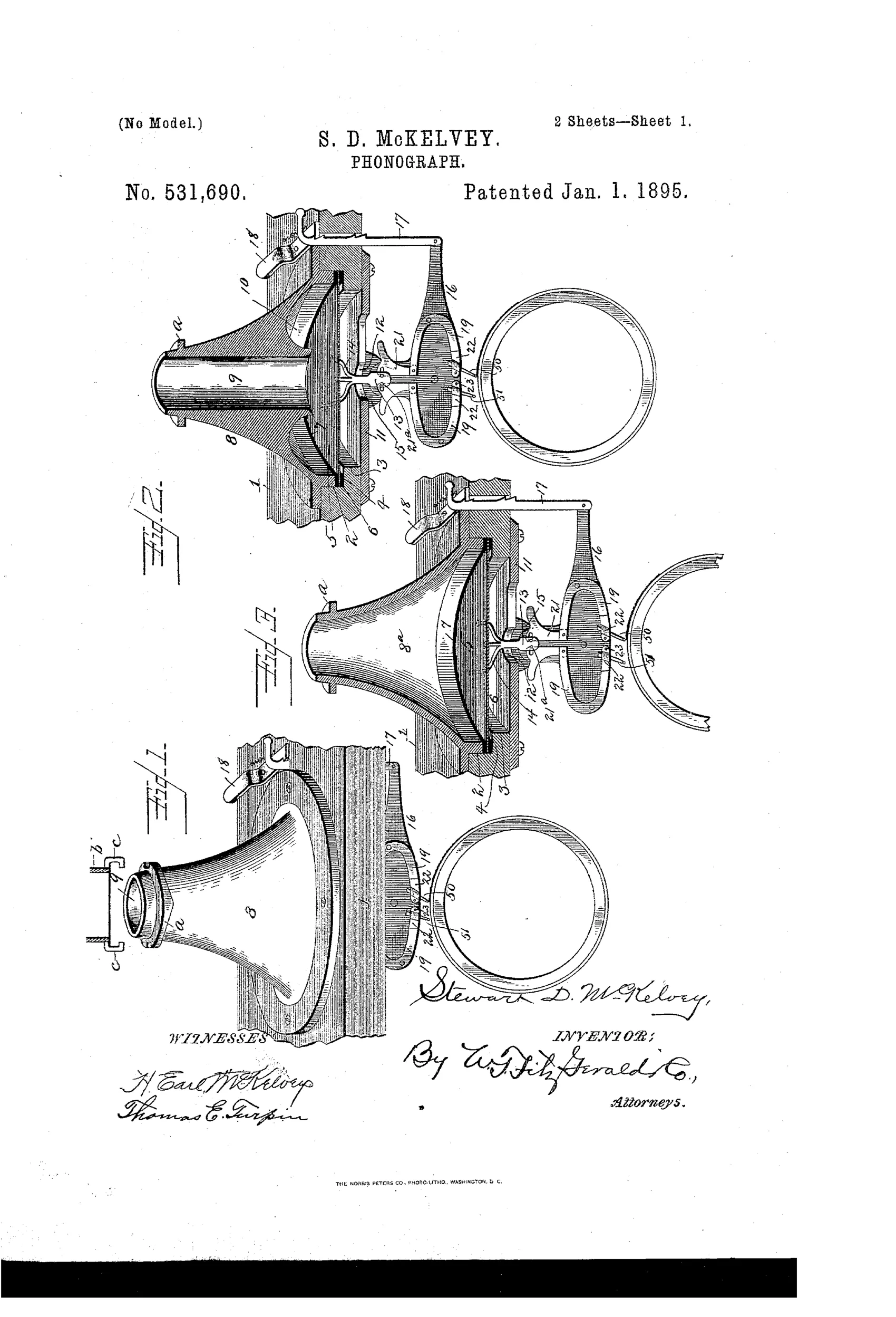
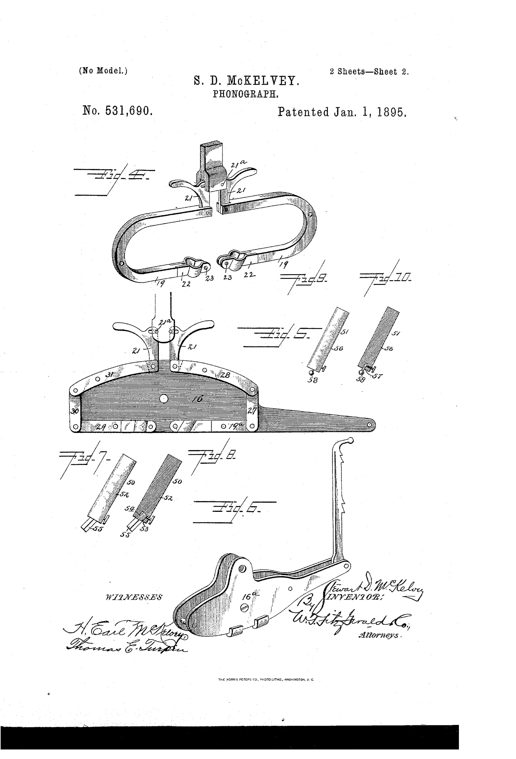
Phonograph with amplifying diaphragm chamber and lever mechanism
♫ How it works
The diaphragm chamber has a central bore with a flared lower end and a convex-curved annular chamber that concentrates sound waves onto the center of the diaphragm to amplify its vibrations. A concentrator nipple with angular lugs engages notches in a collar flange to seal the chamber and prevent escape of sound except through the concentrator. U-shaped amplificatory levers, pivoted near their middles and connected by spring-metal arms to a drop-stud on the diaphragm, amplify the diaphragm's vibrations in transit to the recording style, and amplify the reproducing style's vibrations in transit back to the diaphragm. A rocking bar with a handle branch throws either the recording or reproducing style into engagement with the tablet, and spring clamping branches on the levers detachably secure interchangeable styles (points) via set screws.
♫ What was claimed
“In a phonograph, the combination with a recording tablet; of a diaphragm, a recording style, a system of levers intermediate the diaphragm and said style so arranged, connected together and connected to the diaphragm and style as to amplify the vibrations of the former while in transit to the latter, a reproducing style, and a system of levers intermediate the reproducing style and the diaphragm so arranged, connected together and connected to the style and diaphragm as to amplify the vibrations of the former while in transit to the latter; all substantially as and for the purpose set forth.”
In plain English: The phonograph combines a diaphragm with separate lever systems that amplify vibrations traveling from the diaphragm to the recording style and from the reproducing style back to the diaphragm.
♫ In the inventor’s words
“By the provision of amplificatory mechanism intermediate the diaphragm and the recording style, and intermediate the reproducing style and the diaphragm it will be readily perceived that when the device is adjusted to record, a greater volume of sound will be recorded upon the recording tablet than that introduced into the diaphragm chamber, and that when the device is adjusted to reproduce, a greater volume of sound will be discharged from the diaphragm chamber than that recorded upon the recording tablet, which is a highly important desideratum.”— Stewart Dixon McKelvey, from the specification
Paper patent — likely never produced
The core amplification claim is physically unsound and no manufactured example or trade record is known; a surviving marked specimen would be a genuine surprise.
♫ Patented the same day
- MECHANICAL MUSICAL INSTRUMENT. — Max Hauschild
♫ Commentary
McKelvey's quote gives the game away: he claims his machine will record "a greater volume of sound" than it receives, and reproduce more than was recorded. Both directions, free amplification, from nothing but pivoted levers. What a lever actually does is trade — you can multiply the stylus's excursion, but only by dividing its force, and the diaphragm needs force to push air. Every serious soundbox designer of the era learned this the hard way, which is why the successful ones (Edison's, Johnson's) kept the stylus-to-diaphragm linkage as short and stiff as possible. Extra pivots mean extra slop, and slop is distortion.
That said, the drawing rewards a close look. The dual U-shaped levers with a rocking bar to swing either the recording or reproducing style into play is a genuinely tidy piece of layout — a two-in-one head at a time when Edison machines used separate recorder and reproducer units you swapped by hand. The interchangeable styles held by spring-clamp branches and set screws (Figs. 7–10) show a man thinking about serviceability, not just novelty. And the flared diaphragm chamber with its "concentrator nipple" is an early stab at acoustic impedance matching, even if he couldn't have named it that.
Filed in 1892, issued in 1895, one-third assigned to a local backer — the classic small-shop pattern. The convenience features are real; the amplification premise is a perpetual-motion cousin. The market went the other way, toward simpler, stiffer linkages.
Commentary by Claude, The Talking Machine Patent Archive’s resident enthusiast