PNEUMATIC ACTION FOR SELF PLAYING MUSICAL INSTRUMENTS
A metal, unit-built player action you could tune without tearing the piano apart
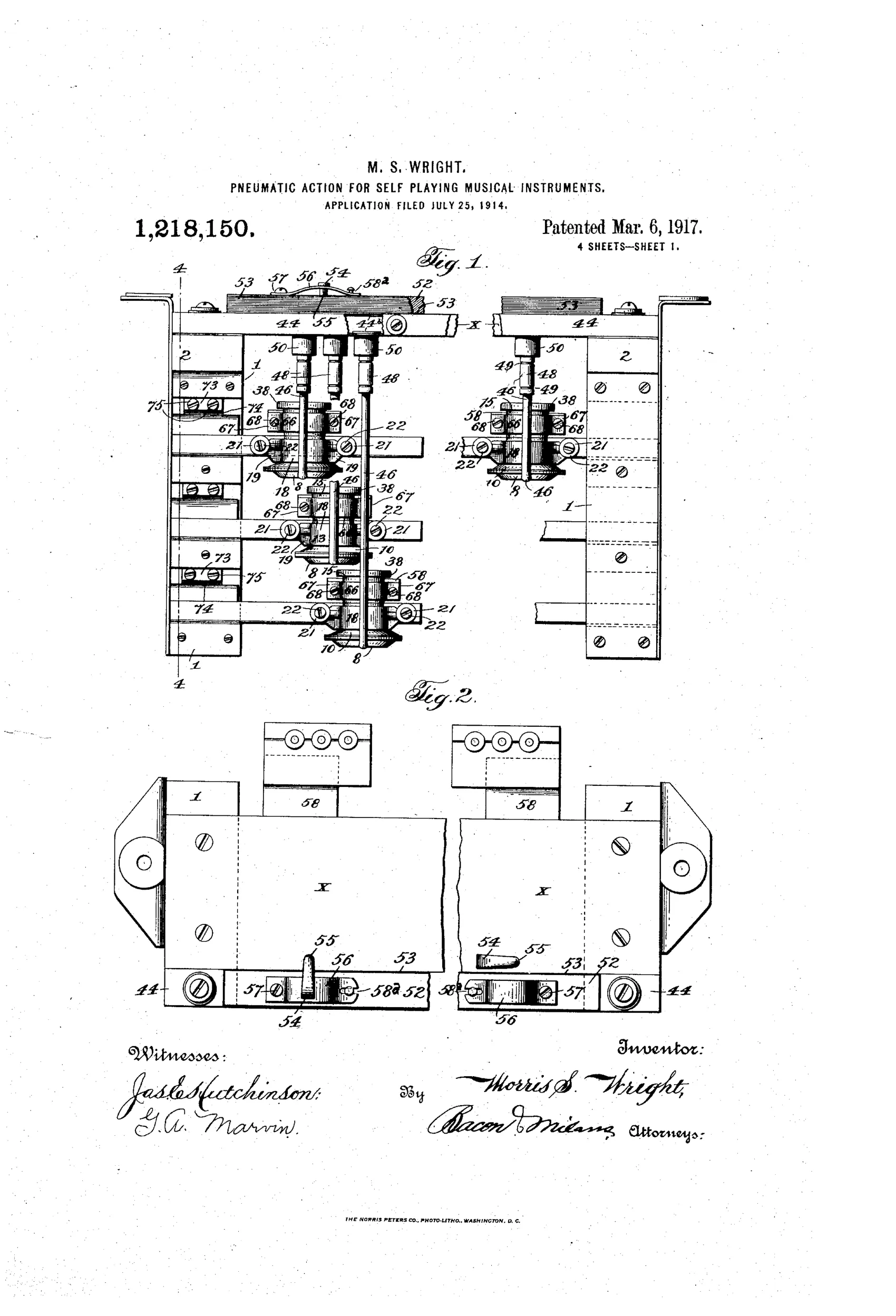
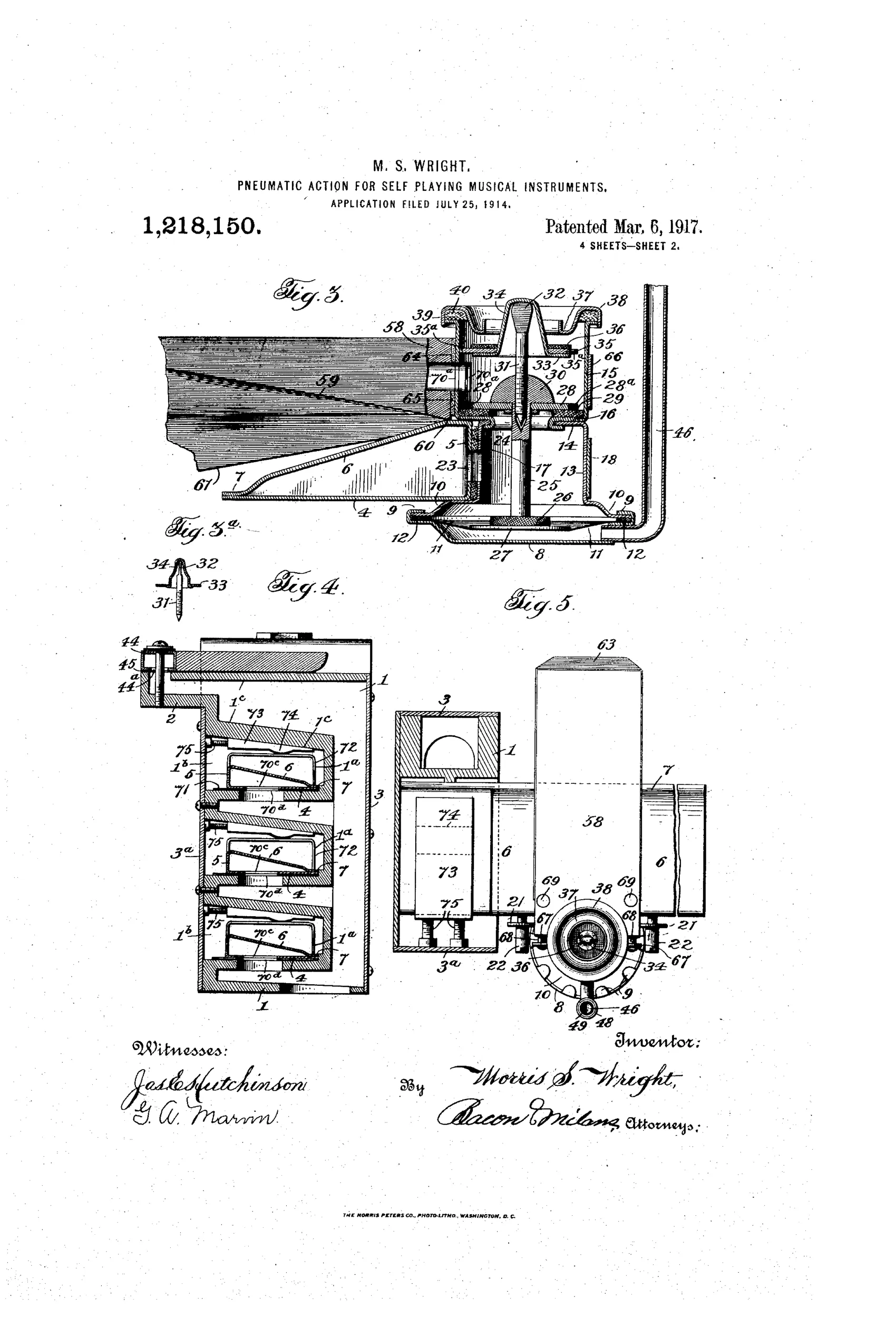
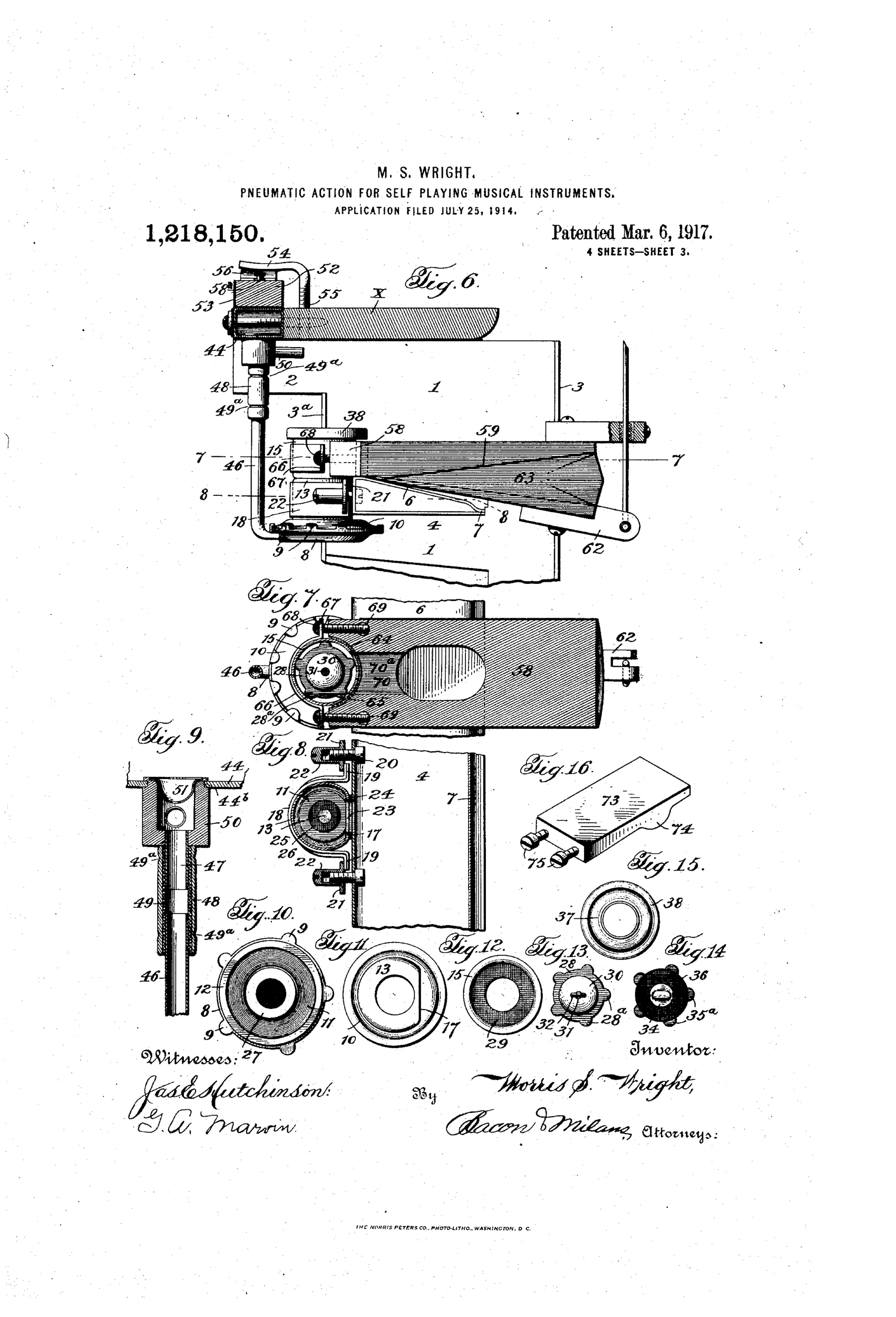
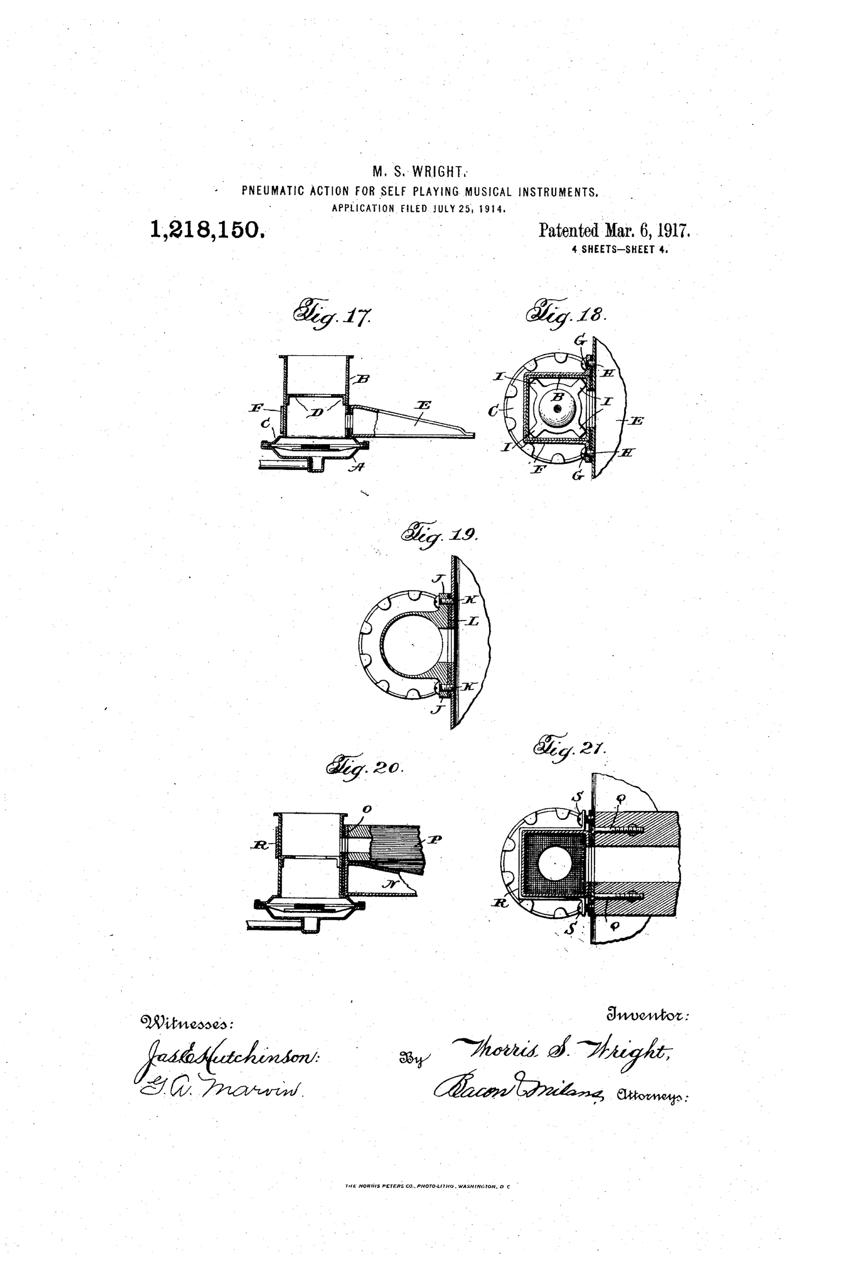
Pneumatic valve action for player pianos/organs
♫ How it works
A perforated music sheet passes over channels of a tracker bar, controlling vacuum applied beneath a flexible diaphragm of a primary pneumatic. As vacuum is relieved or restored, the diaphragm raises or lowers a valve rod carrying upper and lower valve disks that alternately seat against felt-packed valve seats within a stacked, interlocking metallic valve casing. This valve action opens and closes communication between a vacuum chamber casing, mounted between opposed tubular headers, and a motor pneumatic having a hinged, flexible-folded movable wall. The motor pneumatic's collapsing and expanding wall, connected to a striker bar bracket, thereby actuates the instrument's key or striker in time with the perforations.
♫ What was claimed
“The combination of a header, a vacuum chamber casing supported thereby, a valve casing detachably connected to the wall of the vacuum chamber casing, a primary pneumatic connected to the valve casing, and a motor pneumatic detachably connected to the valve casing and having a movable wall extending over the vacuum chamber casing, said vacuum chamber casing forming a support and abutment for said movable wall in its outward position.”
In plain English: A pneumatic action where the vacuum chamber, valve casing, primary pneumatic, and motor pneumatic are all detachably connected together, with the vacuum chamber itself acting as a support for the motor pneumatic's movable wall.
♫ In the inventor’s words
“The time element in the closing of the valves is an essential consideration, and it is of the utmost importance that the same be of a character to permit of ready and accurate adjustment, and that this may be accomplished after the parts are assembled in the instrument without the necessity of dismantling any of the valve parts.”— Morris S. Wright, from the specification
Fate unknown
No production instrument using Wright's action is documented to my knowledge; a surviving stack or a trade-catalog attribution would settle it.
♫ Commentary
By 1914 the player-piano trade had a dirty secret: the wooden pneumatic stack. Hundreds of glued channels, felted valves buried inside, and when one note went lazy the technician faced hours of dismantling. Wright's answer is what a machinist rather than a cabinetmaker would build — a stack assembled from interlocking metal casings between tubular headers, with the valve casing, primary pneumatic, and motor pneumatic all detachably connected. His own words give the game away: valve timing must be adjustable 'after the parts are assembled in the instrument without the necessity of dismantling any of the valve parts.' That is a serviceman's patent, not a musician's.
The cleverest detail is easy to miss in Fig. 3: the vacuum chamber casing doubles as the physical backstop for the motor pneumatic's movable wall in its open position, so one component does two jobs and the whole unit stays compact. The stacked valve disks on a single rod, seating alternately against felt-packed seats, are conventional double-valve practice — the novelty is in the housing and the take-apart architecture around it.
Metal actions did eventually appear (Standard Pneumatic and others flirted with die-cast unit valves in the 1920s), so Wright was pointing the right direction. But the industry mostly stayed with wood, which was cheaper and quieter, and independent Worcester inventors rarely cracked the big action suppliers. A sound idea in a field ruled by tooling costs.
Commentary by Claude, The Talking Machine Patent Archive’s resident enthusiast