The Talking Machine Patent Archive

Patents you could hear

Player piano

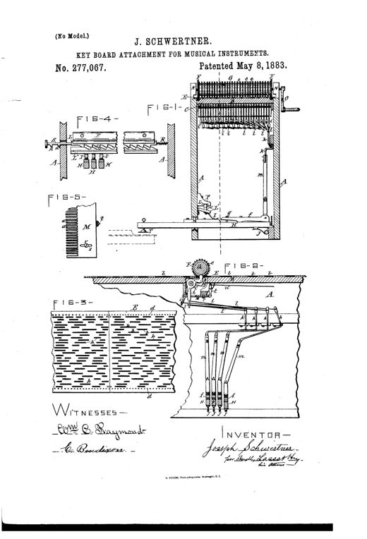
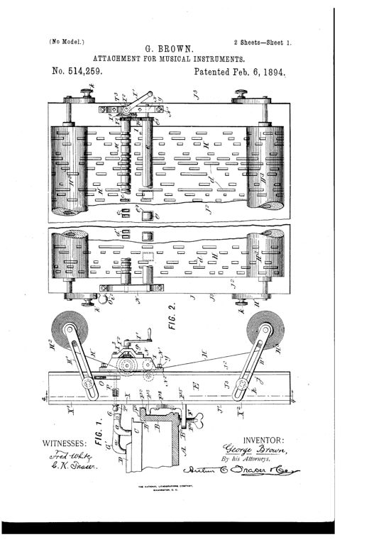
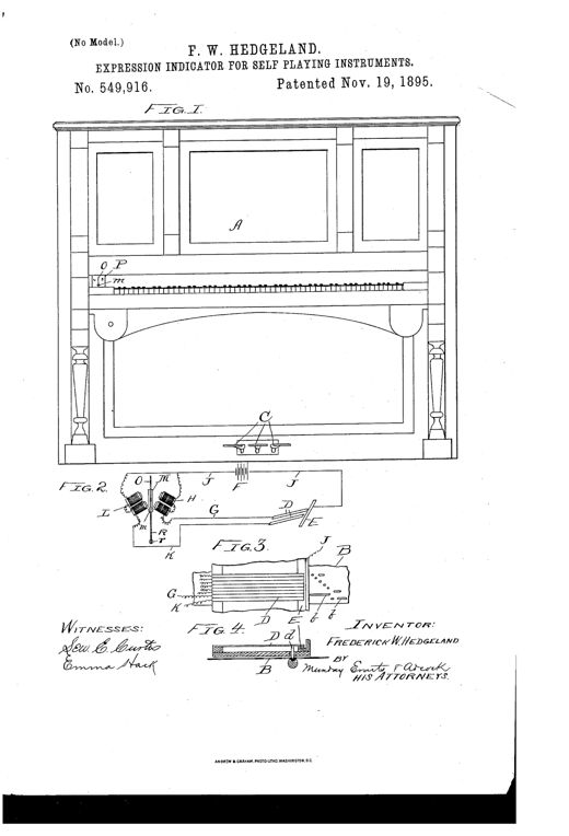
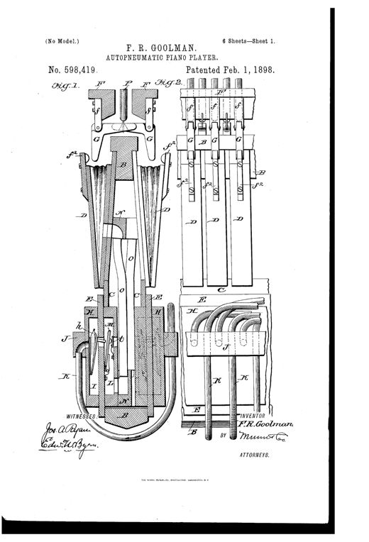
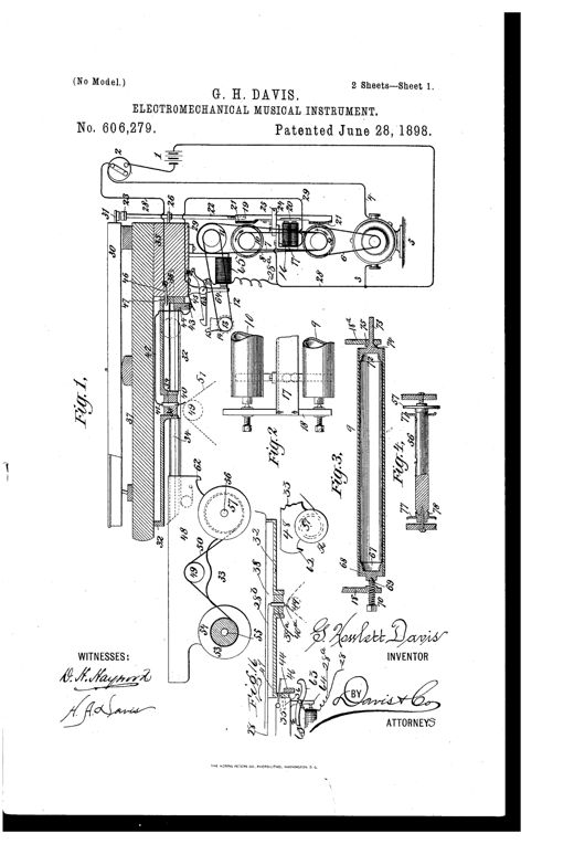
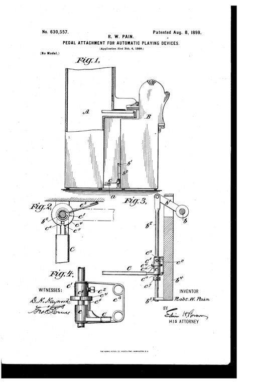
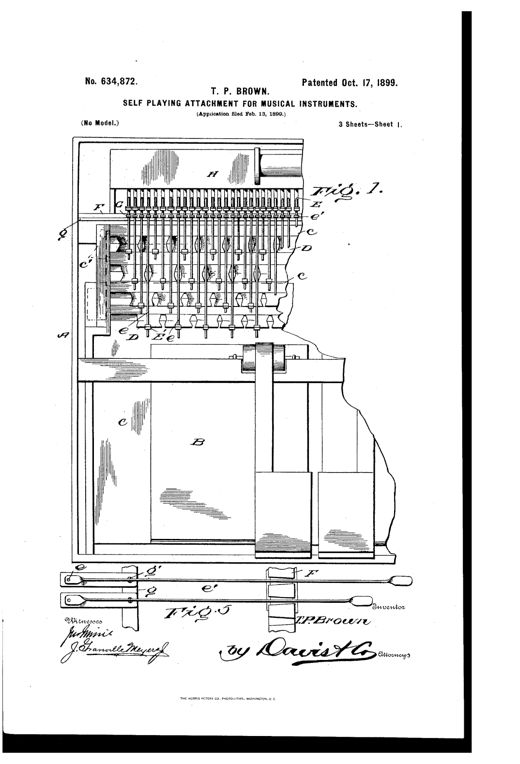
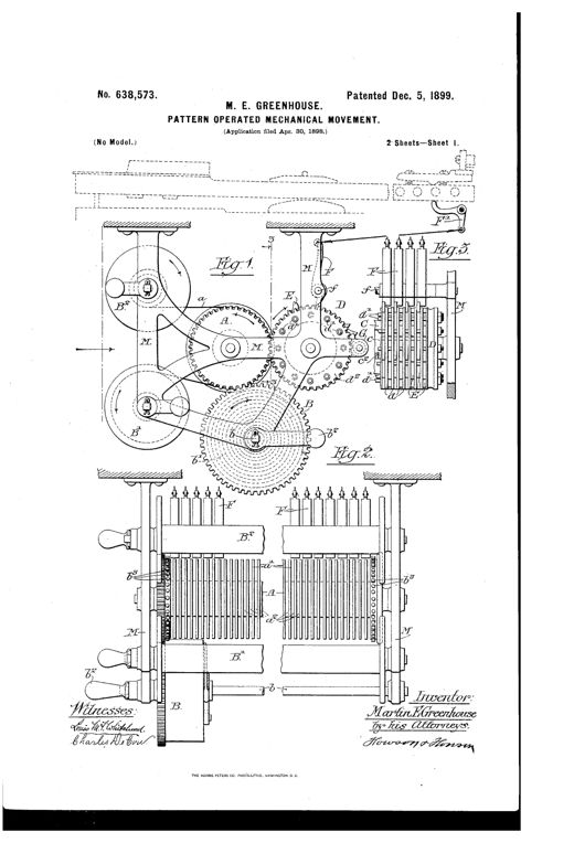
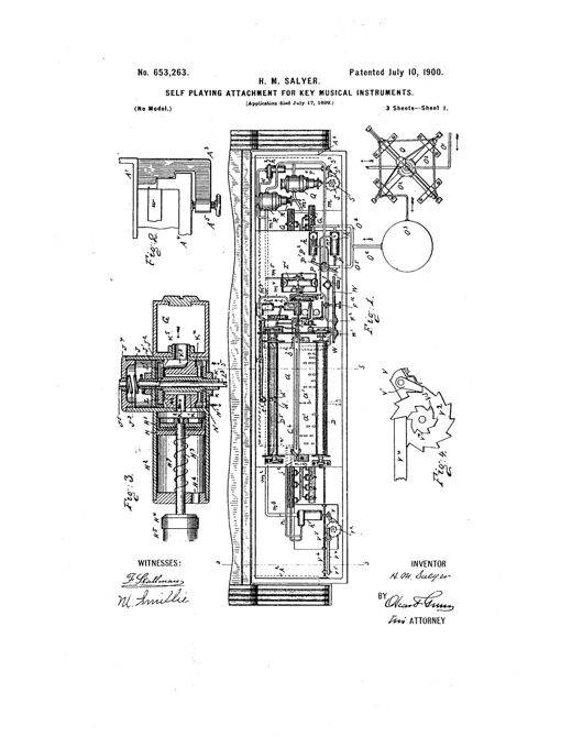
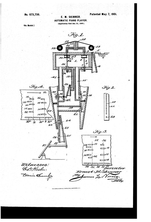
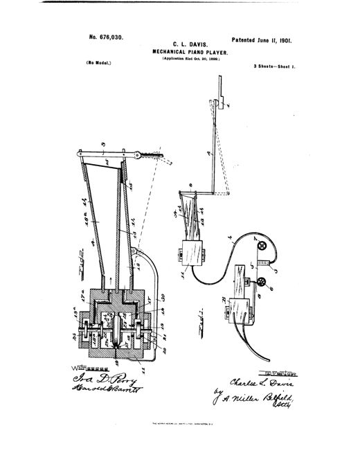
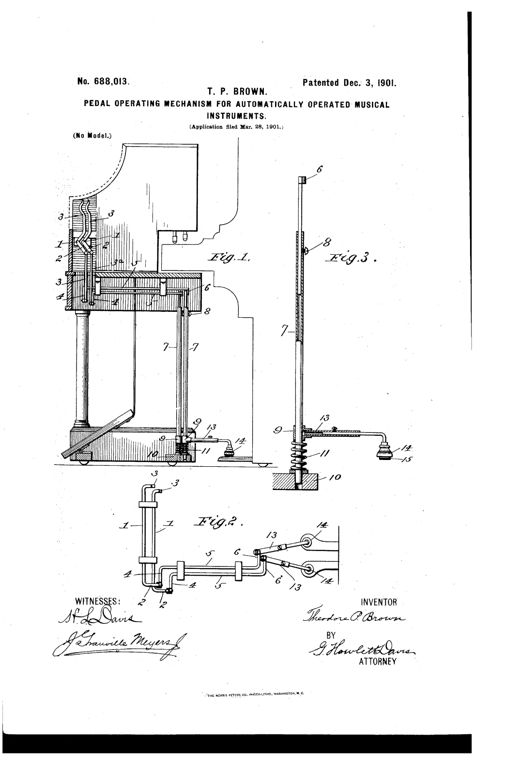
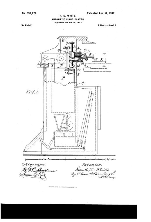
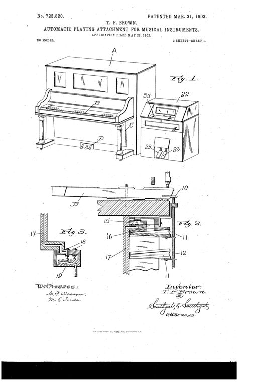
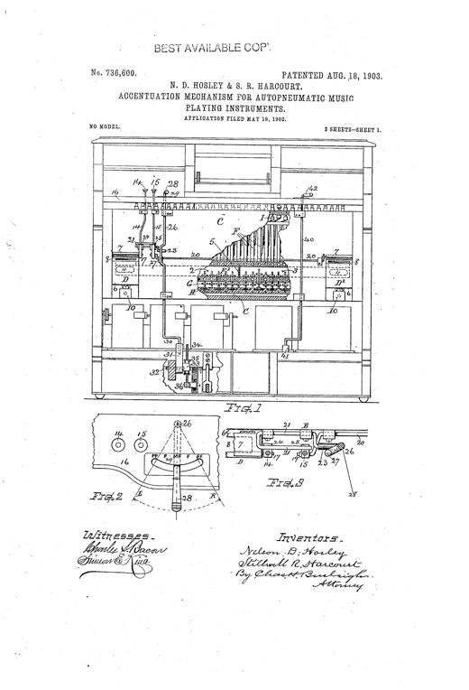
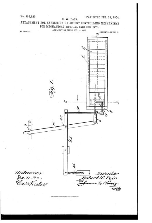
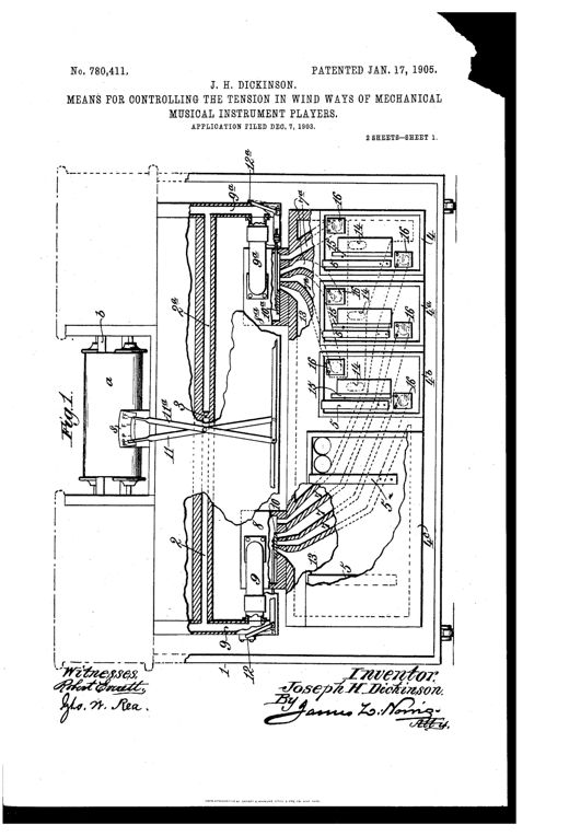
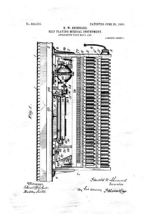
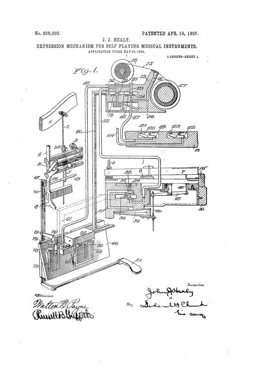
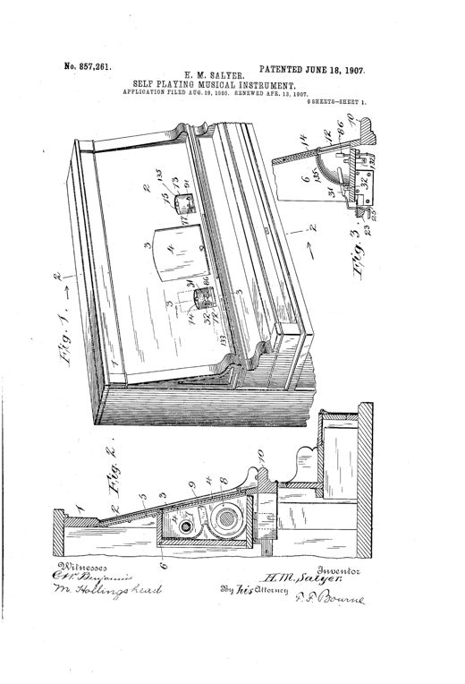
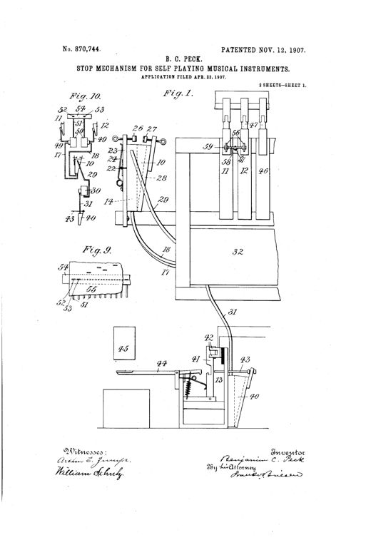
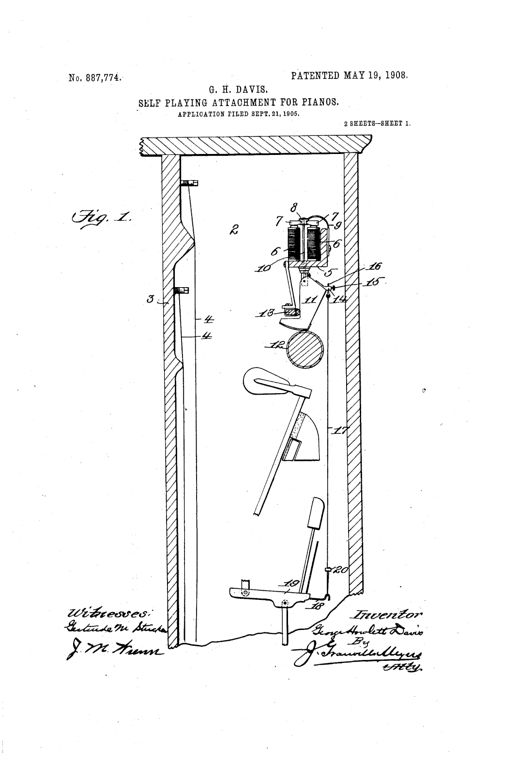
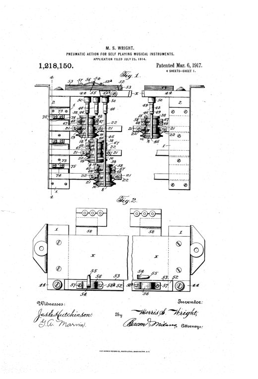
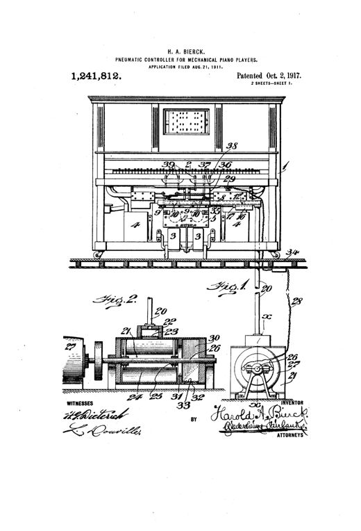
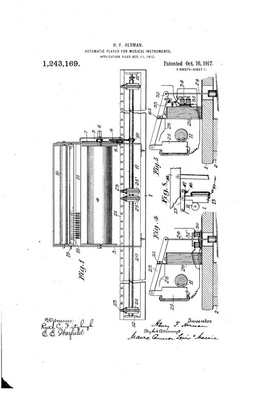
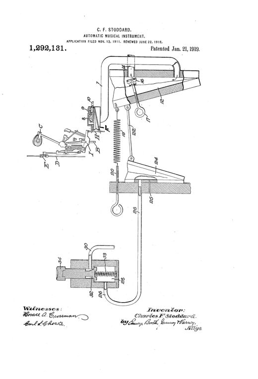
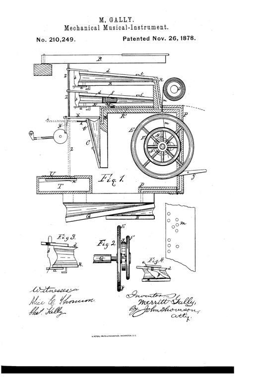
Technical patent drawing showing a complex pneumatic player-piano mechanism with labeled keys, ducts, a large flywheel, crank handle, and perforated music-sheet chamber, alongside smaller detail figures of valve components.IMPROVEMENT IN MECHANICAL MUSICAL INSTRUMENTSMerritt Gally · November 26, 1878Technical patent drawing showing a boxed mechanism with a hand-cranked roller drawing a perforated paper sheet over rows of pivoted levers, connected via rods and elbow-levers to spring-loaded hammers that strike piano keys below.KEY-BOARD ATTACHMENT FOR MUSICAL INSTRUMENTSJoseph Schwertner · May 8, 1883Patent drawing of a rectangular wooden frame mounted atop a piano keyboard, showing rows of pivoted hammers, a perforated paper music sheet threaded over rollers at top and bottom, and a hand crank with gears driving the sheet across the hammer tips.ATTACHMENT FOR MUSICAL INSTRUMENTS.George Brown · February 6, 1894Front elevation of an upright piano case with three paneled windows above the keyboard, a small pointer and dial labeled O and P near the treble end of the keys, three pedals below, and accompanying schematic diagrams of the electric circuit, perforated control strip, and circuit-closer mechanism beneath the main drawing.EXPRESSION-INDICATOR FOR SELF-PLAYING INSTRUMENTSFrederick W. Hedgeland · November 19, 1895Cutaway front elevation of an upright piano cabinet revealing the pneumatic player mechanism, including vertical striking bellows, valve-board, tubing to a tracker bar, paired music rolls in a lower drawer, and a flywheel-driven exhaust pump at the base.AUTOPNEUMATIC PIANO-PLAYERFred R. Goolman · February 1, 1898Patent drawing showing a piano attachment with a battery, electric motor, rotating friction drums, a bank of electromagnets with striker rods, a perforated paper music roll and take-up spool, and a sliding drawer contact mechanism, with the inventor's cursive signature at bottom.ELECTROMECHANICAL MUSICAL INSTRUMENT.George Howlett Davis · June 28, 1898Patent drawing showing a piano casing labeled A next to an automatic playing device labeled B, with a detailed pedal-linkage mechanism including a shaft, collars, spring, and pedal C illustrated in four separate figures.PEDAL ATTACHMENT FOR AUTOMATIC PLAYING DEVICES.Robert W. Pain · August 8, 1899Patent drawing of a self-playing piano attachment showing a row of vertical key-levers with pneumatic bellows, an exhaust trunk system, and a tracker-board with radiating air-ducts, alongside a side-sectional view of the case with bellows, treadles, and adjustable key-lever bar.SELF-PLAYING ATTACHMENT FOR MUSICAL INSTRUMENTSTheodore Parker Brown · October 17, 1899Mechanical drawing of a patent showing a spool-fed perforated paper pattern engaging a toothed carrier gear that drives a cylinder studded with spring-loaded dogs, which strike a row of pivoted levers connected to piano keys, with detail insets of the fixed hub, cam, dog, ring, jack, and a section of the punched pattern sheet.PATTERN-OPERATED MECHANICAL MOVEMENTMartin E. Greenhouse · December 5, 1899A detailed mechanical patent drawing showing a long rectangular casing mounted over a piano keyboard, containing rows of numbered valves, plungers, rollers, cog-wheels, and a governor mechanism connected by tubing to an external air compressor and tank.SELF PLAYING ATTACHMENT FOR KEY MUSICAL INSTRUMENTS.Harry M. Salyer · July 10, 1900Cutaway mechanical drawing of a player-piano pneumatic mechanism showing the vacuum chamber, key-pneumatics, tracker board with a perforated paper music roll passing over it, feeder bellows, and pedal linkage, alongside detail views of the tracker board slots and a music-sheet with rows of numbered perforations.AUTOMATIC PIANO-PLAYERErnest M. Skinner · May 7, 1901Patent drawing showing a boxed pneumatic mechanism with bellows chambers, diaphragms, valve spindles, and a lever rod connected to a piano key, alongside a wheel-driven motor variant for advancing the music roll.MECHANICAL PIANO-PLAYERCharles L. Davis · June 11, 1901Patent drawing showing a piano's interior with rock-shafts, hand levers, telescoping vertical bars, springs, and pedal-depressing arms mechanically linked to depress the piano pedals.PEDAL-OPERATING MECHANISM FOR AUTOMATICALLY-OPERATED MUSICAL INSTRUMENTSTheodore Parker Brown · December 3, 1901Cutaway side-view engineering drawing of an upright piano-player cabinet showing the adjustable finger mechanism, guide rods, standards, tracker bar, bellows chest, and pedal-driven pump linkage inside the case.AUTOMATIC PIANO-PLAYERFrank C. White · April 8, 1902Patent drawing of an upright piano with a separate adjacent cabinet housing the pneumatic tracker-board and paper roll mechanism, with detailed cross-section views of the internal pneumatic bellows and key-lever linkages.AUTOMATIC PLAYING ATTACHMENT FOR MUSICAL INSTRUMENTS.Theodore P. Brown · March 31, 1903Patent drawing of a player-piano cabinet's internal pneumatic mechanism, showing tracker board, choker valve boxes, operating pneumatics, and pedal-actuating rods, with detail insets of the choker valve and control lever assembly.ACCENTUATION MECHANISM FOR AUTOPNEUMATIC MUSIC-PLAYING INSTRUMENTS.Nelson D. Hosley and Stillwell R. Harcourt · August 18, 1903Patent drawing of a player-piano expression-control attachment showing a gated box with multiple air passages, a pivoting operating handle with a dynamics scale from pianissimo to fortissimo, and linked rods and springs connecting to a supplemental valve.ATTACHMENT FOR EXPRESSION OR ACCENT CONTROLLING MECHANISMS FOR MECHANICAL MUSICAL INSTRUMENTS.Robert W. Pain · February 23, 1904Patent drawing of a player-piano mechanism showing a paper music roll, tracker board, divided wind-chest with valve casings, and two pivoted hand levers positioned near an indicating scale for controlling bass and treble tension independently.MEANS FOR CONTROLLING THE TENSION IN WIND WAYS OF MECHANICAL-MUSICAL-INSTRUMENT PLAYERSJoseph H. Dickinson · January 17, 1905Front elevation of a piano's interior mechanism showing rows of cylindrical electromagnets, transmission rods, and a perforated paper roll assembly mounted beneath an open keyboard, with a small electric motor and driving wheel at upper right.SELF-PLAYING MUSICAL INSTRUMENT.Harold W. Shonnard · June 26, 1906Exploded mechanical drawing of a player-piano expression mechanism showing a paper music roll feeding over a tracker-board connected via tubing to a bank of pneumatic bellows, valves, and levers that operate the piano's hammer-rail and damper system, with a foot-pedal lever at the bottom.EXPRESSION MECHANISM FOR SELF-PLAYING MUSICAL INSTRUMENTS.John J. Healy · April 16, 1907An exploded perspective drawing of the upper interior of a player piano, showing the sliding door and roll receptacle above the keyboard, rows of numbered pneumatic bellows and wippen-engaging arms, and a side detail of the governor and valve assembly for the paper-roll drive motor.SELF-PLAYING MUSICAL INSTRUMENT.Harry M. Salyer · June 18, 1907Patent drawing showing a front elevation of a player-piano stop mechanism with labeled bellows, ducts, valves, and switch components mounted on a wooden frame, alongside detail figures of the auxiliary bellows and duct-bridge.STOP MECHANISM FOR SELF-PLAYING MUSICAL INSTRUMENTS.Benjamin C. Peck · November 12, 1907Patent drawing of a piano's upper casing showing a self-playing mechanism with paired electromagnets, a rocking armature, a shoe pressing against a spinning roller, and a tape running down to the piano's hammer action and keys.SELF-PLAYING ATTACHMENT FOR PIANOS.George Howlett Davis · May 19, 1908Technical patent drawings of a player-piano pneumatic action showing stacked metal headers, valve casings with numbered valve disks and rods, a vacuum chamber casing, and a hinged motor pneumatic with a striker bar bracket, along with detail views of individual valve components and wedge blocks.PNEUMATIC ACTION FOR SELF PLAYING MUSICAL INSTRUMENTSMorris S. Wright · March 6, 1917Patent drawing of an upright player piano cabinet with exposed pneumatic mechanism including foot treadles, air reservoirs, valve conduits, and a motor-driven blower assembly connected beneath the floor.PNEUMATIC CONTROLLER FOR MECHANICAL PIANO-PLAYERSHarold A. Bierck · October 2, 1917Patent drawing of an electromagnetic player-piano mechanism showing a rotating shaft, rows of magnets on pivoted walking beams, a tracker bar with a bristle brush contacting a perforated paper music roll, and thrust rods connecting to the piano keys.AUTOMATIC PLAYER FOR MUSICAL INSTRUMENTSHenry F. Herman · October 16, 1917A technical line drawing of a player-piano mechanism showing a hammer-and-key action linked by rods and springs to a horn-shaped pneumatic bellows, a coil spring, a secondary tilted pneumatic labeled 24, and a small valve cylinder with a manual button labeled 34 at the bottom, all connected by numbered ducts and levers.AUTOMATIC MUSICAL INSTRUMENTCharles F. Stoddard · January 21, 1919