AUTOMATIC PLAYING ATTACHMENT FOR MUSICAL INSTRUMENTS.
The key-pushers hide inside the piano; only the roll box sits outside
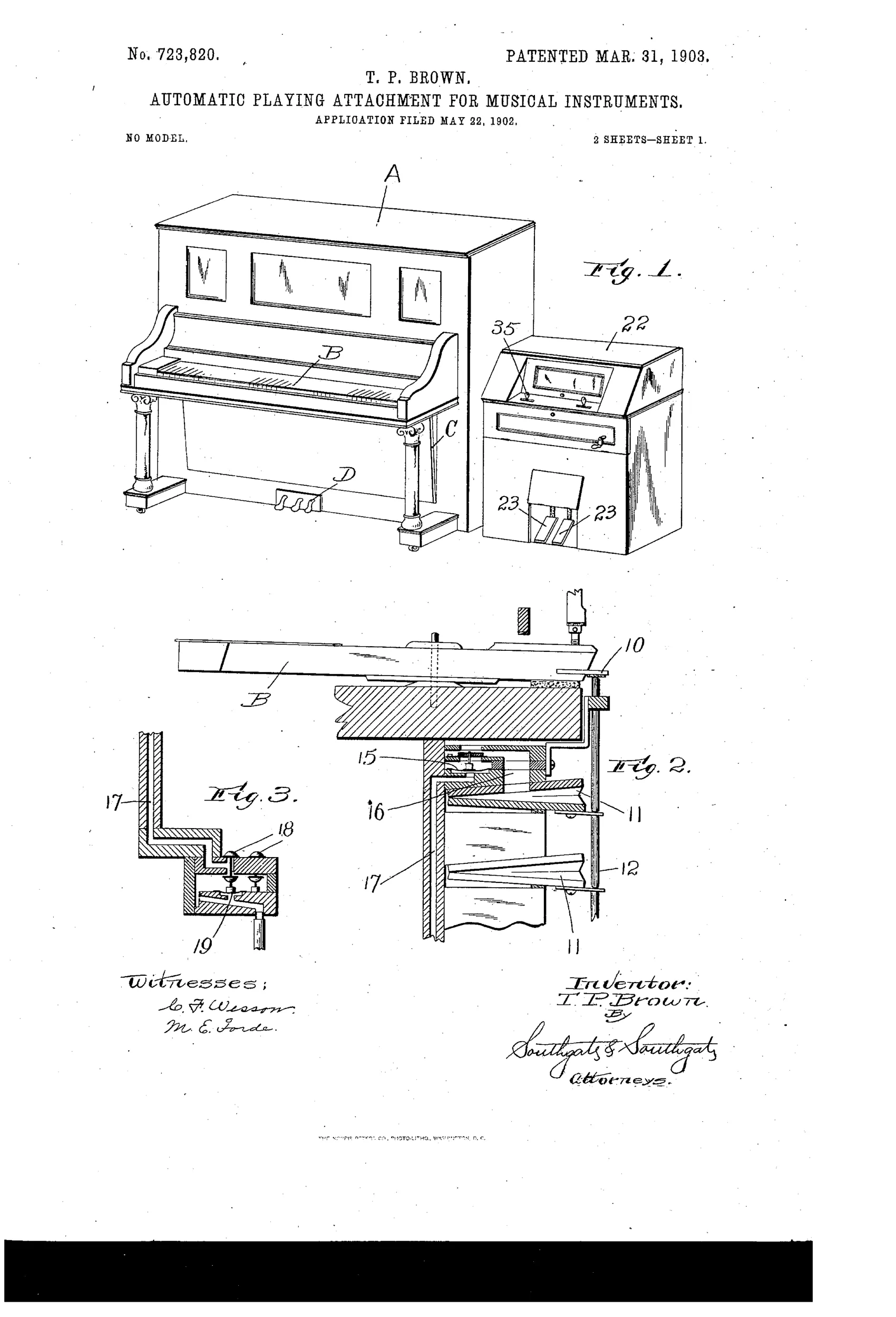
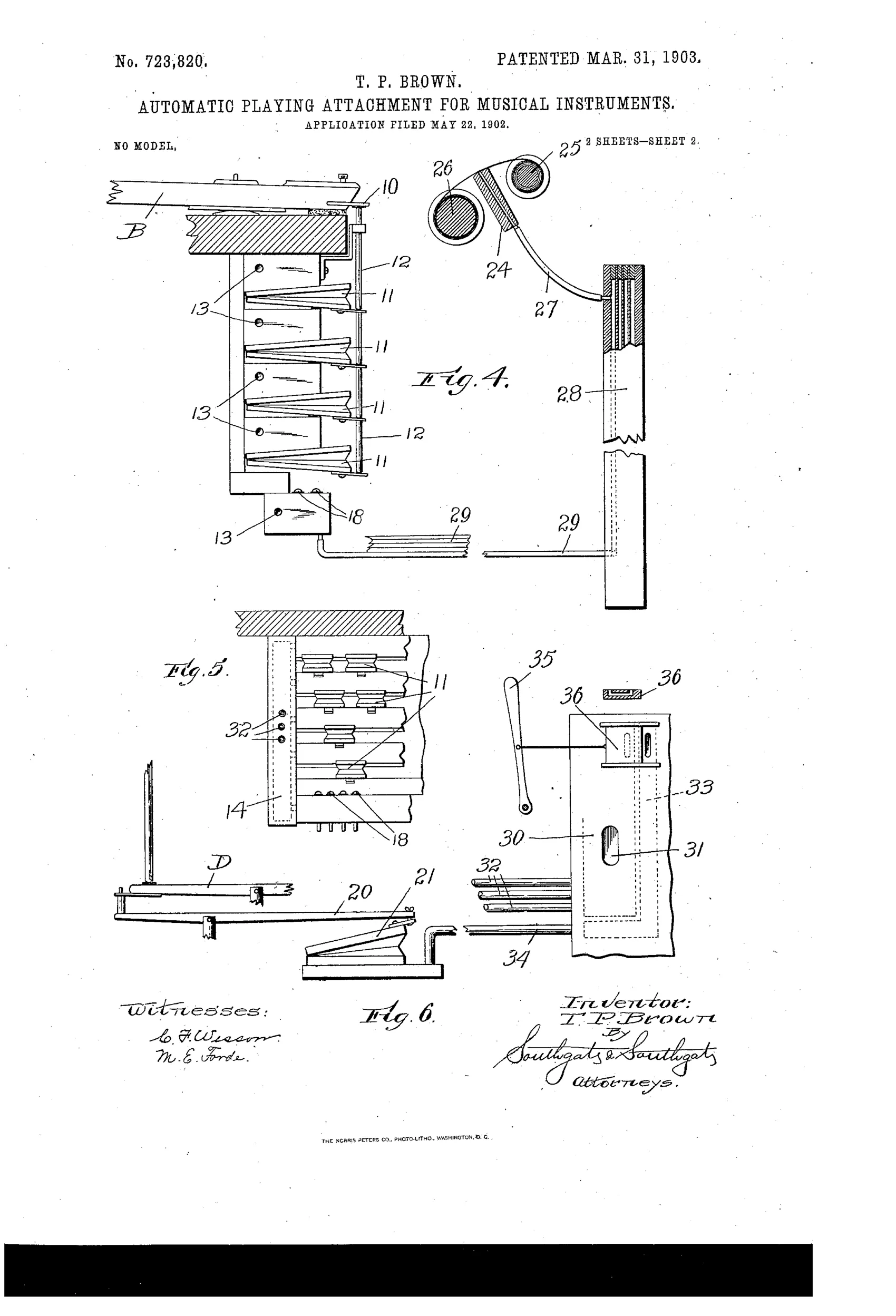
Pneumatic player-piano attachment in separate side casing
♫ How it works
A bank of main pneumatics is located below the piano key-levers inside the piano casing and lifts the rear ends of the key-levers without blocking normal manual playing. A separate casing set at one end of the piano houses the tracker-board, paper-winding rolls, and bellows-operating pedals. Flexible rubber tubes carry air impulses from the tracker-board across to primary pneumatics, which operate valves controlling the main pneumatics that push the keys. Pedal-operating pneumatics within the piano casing, controlled by a valve in the separate casing, actuate the piano's pedals as the perforated paper roll travels over the tracker-board.
♫ What was claimed
“The combination of a piano-casing, a bank of main pneumatics located below the key-levers, and arranged to lift the rear ends of the key-levers without interfering with the manual operation thereof, a separate casing arranged at one end of the piano, a tracker-board, paper-winding devices and bellows-operating devices mounted in said casing, and connections for controlling the main pneumatics from the tracker-board.”
In plain English: A player-piano mechanism where the key-pushing pneumatics stay inside the piano and don't block normal playing, while the paper roll and bellows are housed in a separate box at one end connected to control the key pneumatics.
♫ In the inventor’s words
“I have found in practice that the main pneumatics may be arranged a considerable distance from the tracker-board without materially diminishing the power of the playing attachment or interfering with the artistic effects produced thereby.”— Theodore P. Brown, from the specification
Fate unknown
Brown was a genuine Worcester player-action manufacturer, but whether this specific side-cabinet configuration reached production is undocumented; a surviving example or catalog listing would settle it.
♫ Commentary
By 1902 the standard way to automate a piano was the push-up 'piano player' — a whole cabinet of felted fingers wheeled up against the keyboard, hammering the keys from outside like a mechanical pianist. Theodore Brown splits the problem differently. He tucks the bank of main pneumatics inside the piano case, under the key-levers, lifting their rear ends — and exiles only the tracker-board, the paper roll, and the foot-pumped bellows to a separate cabinet at the piano's end, connected by flexible rubber tubing.
That split buys two real advantages. The keys stay free for ordinary hand playing — the claim says so explicitly, and it matters, because a push-up blocked the keyboard entirely. And the pneumatic action pushes the levers directly instead of poking the ivories through a second set of fingers, which wastes motion and muddies touch. Brown's remark that the main pneumatics work fine 'a considerable distance from the tracker-board' is the quiet engineering point: primary pneumatics and valves let a whisper of tracker air trigger a strong stroke far away, so the tubing run costs almost nothing.
Brown was no dabbler — he was a Worcester player-action man, and this patent is a stepping stone on the path the whole industry took: from external push-up to fully interior player action. The awkward side cabinet was the transitional compromise; within a few years the roll box moved inside too, and the 'player piano' as we know it arrived.
Commentary by Claude, The Talking Machine Patent Archive’s resident enthusiast