SOUND RECORDING AND REPRODUCING MACHINE
Johnson and Clark's spring-damped soundbox, two years before Victor existed
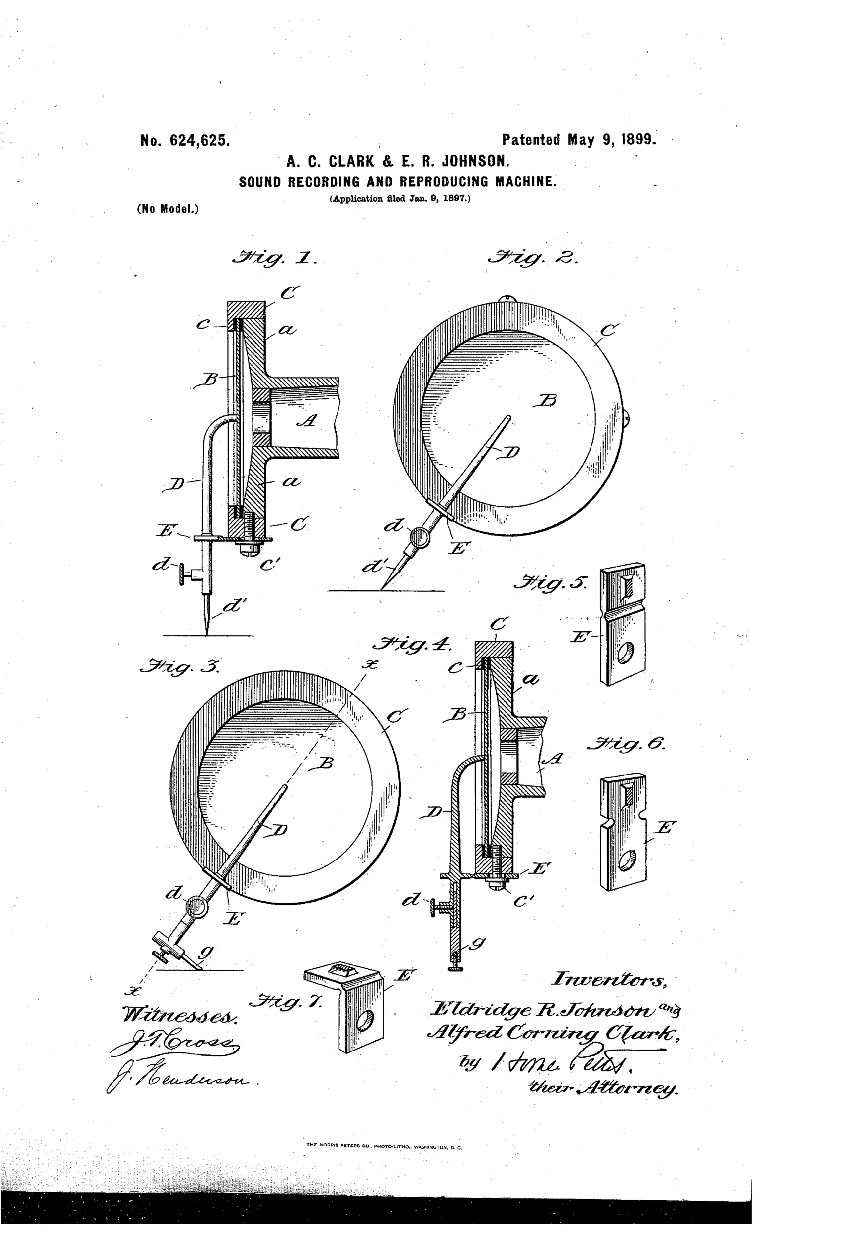
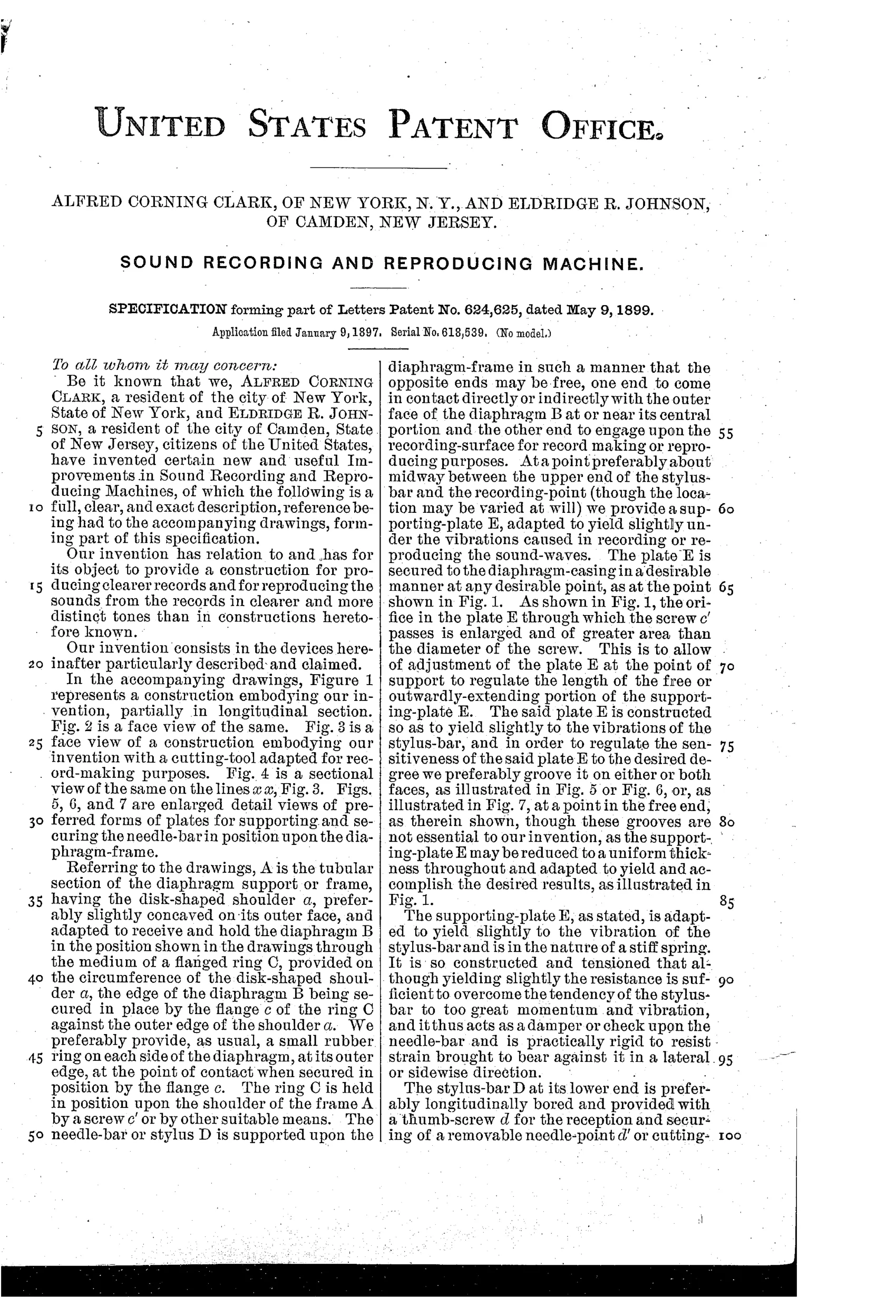
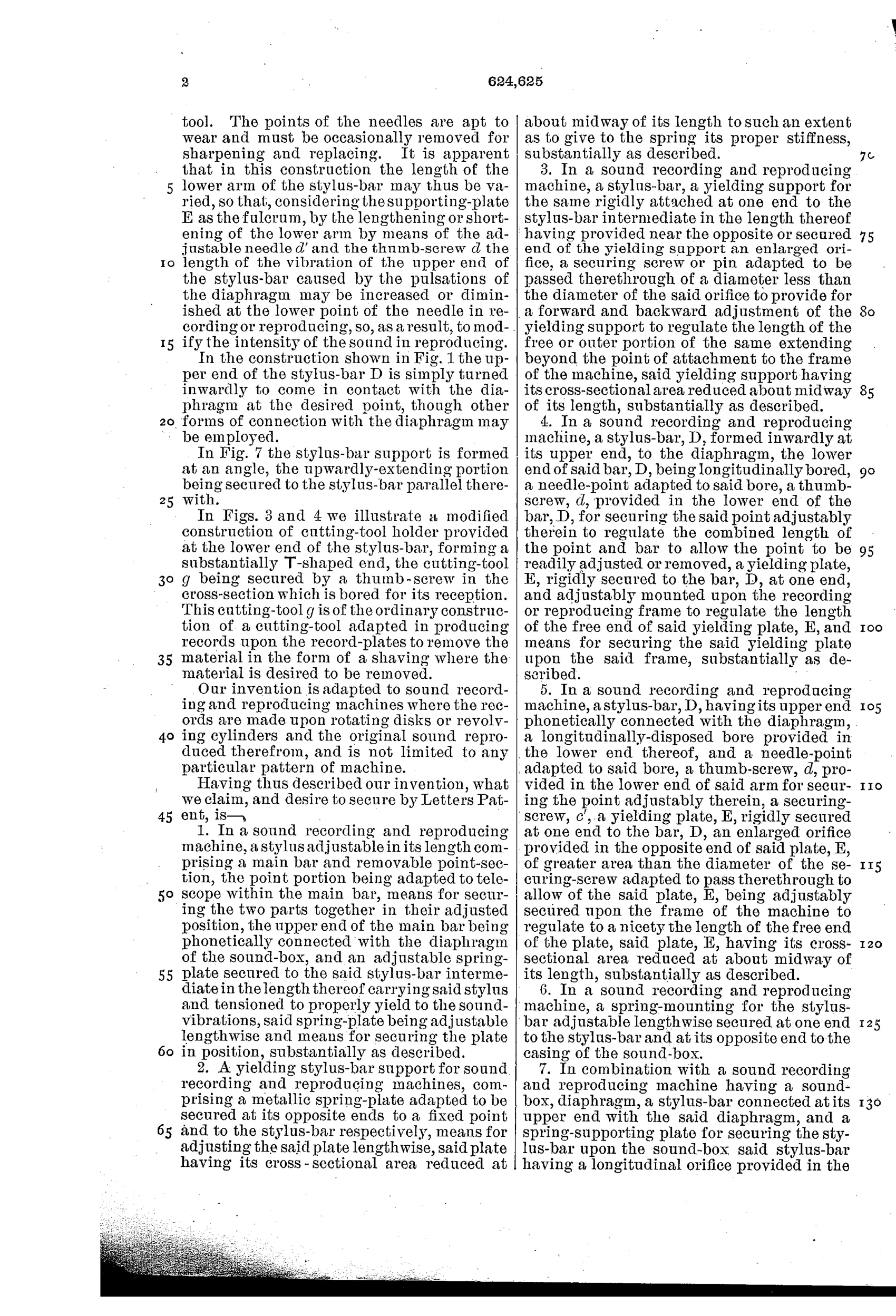

Spring-mounted adjustable stylus bar for phonographs
♫ How it works
A tubular diaphragm frame holds a diaphragm secured by a flanged ring against a disk-shaped shoulder. A stylus bar is connected at its upper end to the diaphragm and is supported partway along its length by a yielding spring plate that acts as a fulcrum and damper. The lower end of the stylus bar is longitudinally bored and fitted with a thumb-screw so a removable needle-point or cutting tool can be adjusted or replaced. By lengthening or shortening the lower arm of the stylus bar via the needle, the vibration amplitude and thus the intensity of reproduced or recorded sound can be regulated.
♫ What was claimed
“1. In a sound recording and reproducing machine, a stylus adjustable in its length comprising a main bar and removable point-section, the point portion being adapted to telescope within the main bar, means for securing the two parts together in their adjusted position, the upper end of the main bar being phonetically connected with the diaphragm of the sound-box, and an adjustable spring-plate secured to the said stylus-bar intermediate in the length thereof carrying said stylus and tensioned to properly yield to the sound-vibrations, said spring-plate being adjustable lengthwise and means for securing the plate in position, substantially as described.”
In plain English: A stylus with a telescoping, length-adjustable needle section connected to the diaphragm, supported midway by an adjustable spring plate that yields to sound vibrations and can be locked in place.
♫ In the inventor’s words
“It is so constructed and tensioned that although yielding slightly the resistance is sufficient to overcome the tendency of the stylus-bar to too great momentum and vibration, and it thus acts as a damper or check upon the needle-bar and is practically rigid to resist strain brought to bear against it in a lateral or sidewise direction.”— Alfred Corning Clark and Eldridge R. Johnson, from the specification
Manufactured and sold
The Clark-Johnson soundbox was produced for Berliner's Improved Gramophone and its lineage runs directly into Victor's reproducers.
♫ Commentary
The names on this patent matter more than the hardware, and the hardware is good. Eldridge Johnson was the Camden machinist then building spring motors for Berliner's gramophone; Alfred Clark was Berliner's associate who would go on to run the Gramophone Company in Europe. Filed in January 1897, this is the pair working out the soundbox problem before the Victor Talking Machine Company was even a rumor.
The mechanical idea is subtle and worth a slow look at Fig. 1. The stylus bar isn't rigidly clamped or freely hinged — it hangs from the diaphragm and passes through a spring plate E partway down its length. That plate does double duty: it's the fulcrum, and it's a damper, yielding just enough to pass sound vibration while killing the bar's tendency to overshoot and ring. The detail figures 5 through 7 show three variations on that plate, which tells you they were tuning it empirically. Meanwhile the lower end is bored to take a telescoping, replaceable needle locked by thumbscrew — and sliding it in or out changes the lever ratio, giving you crude volume control and a disposable point in one stroke.
Collectors know the result as the Clark-Johnson soundbox, fitted to the Improved Gramophone of 1897-98 — the machine in the Nipper painting. This is refinement at exactly the right moment, done by exactly the right hands.
Commentary by Claude, The Talking Machine Patent Archive’s resident enthusiast