PHONOGRAPH.
Edison packs recorder, reproducer, and shaving knife onto one rocking arm
Improved cylinder phonograph recorder-reproducer mechanism
♫ How it works
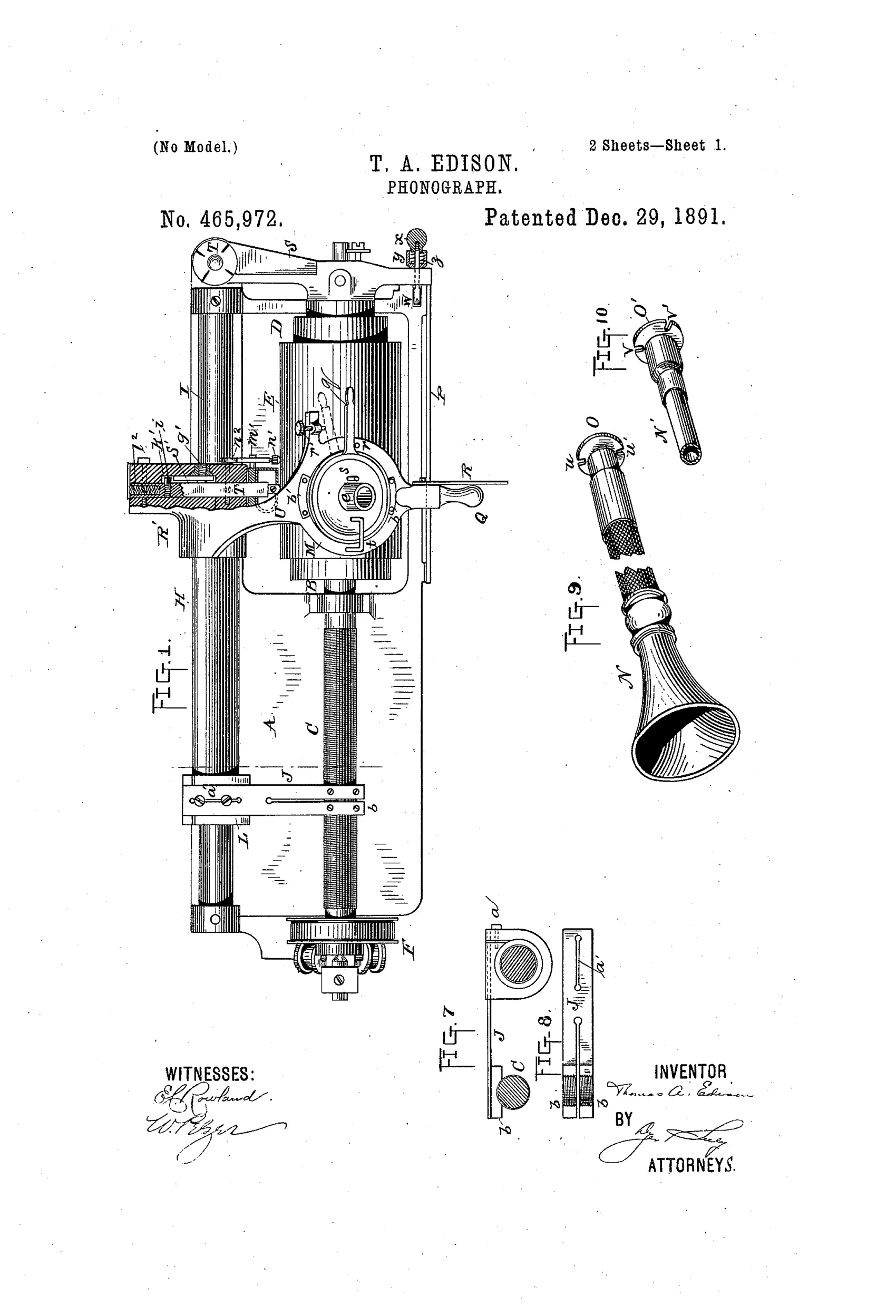
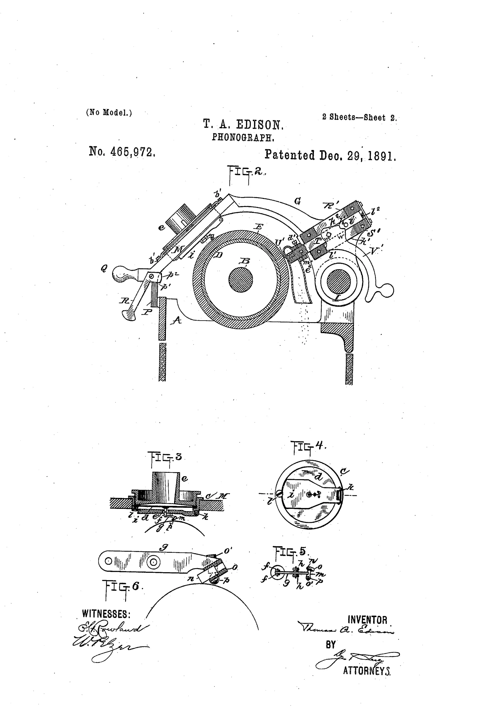
A single diaphragm carries both a gouging recording-point and a spherical reproducing-point on a cross-piece, so a simple turning movement of the holder brings either point into operative contact with the phonogram-cylinder without any adjustment. The rocking holding-arm slides on a rod and carries a split spring feed-arm with divided nut-sections that engage a feed-screw, moving the recorder or reproducer along the rotating cylinder. A loose weight presses on the diaphragm to set proper recording depth and to retard and smooth vibrations transmitted to and from the diaphragm. A separate turning-off knife, spring-biased forward against an adjustable stop, is mounted on the rocking arm to shave the phonogram-blank surface for reuse, with a chute to carry away the shavings and a spring-lock to hold the knife clear of the cylinder when not in use.
♫ What was claimed
“1. In a phonograph, the combination, with a diaphragm, of a recording-point and a separate reproducing-point connected therewith and adapted to be brought alternately into operative relation with the same surface, substantially as set forth.”
In plain English: The patent covers a phonograph diaphragm with both a recording stylus and a separate playback stylus that can be swung alternately into contact with the same cylinder surface.
♫ In the inventor’s words
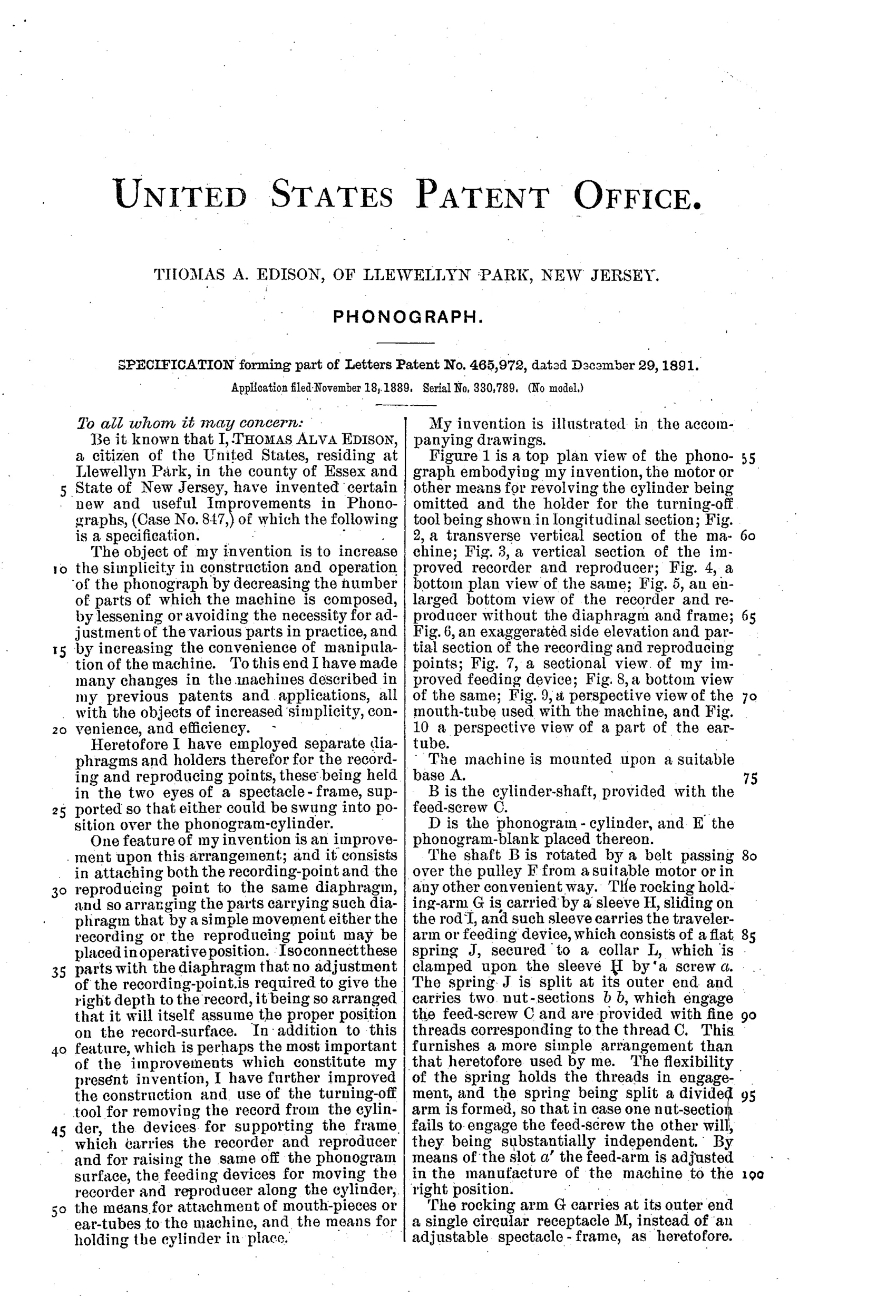
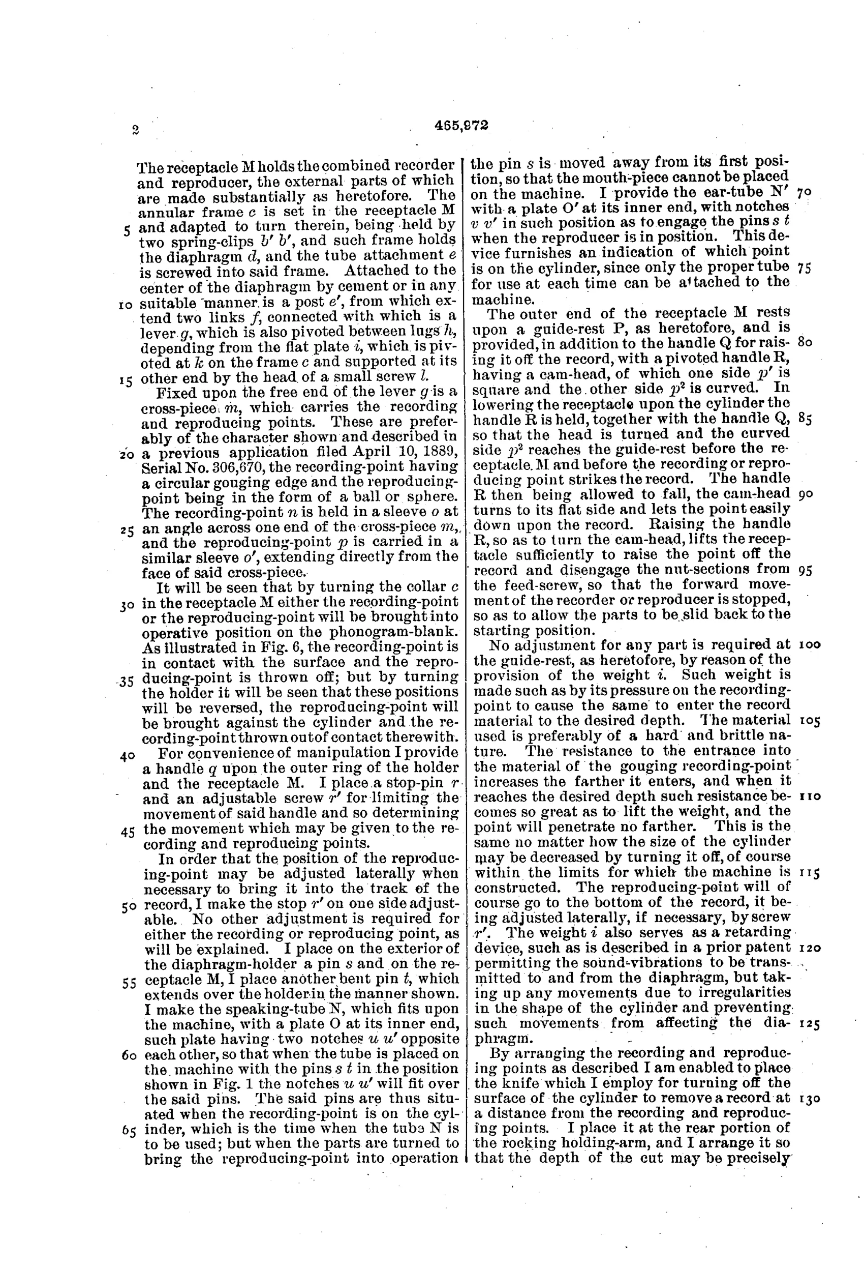
“The resistance to the entrance into the material of the gouging recording-point increases the farther it enters, and when it reaches the desired depth such resistance becomes so great as to lift the weight, and the point will penetrate no farther.”— Thomas A. Edison, from the specification
Manufactured and sold
These features — combined recorder/reproducer, weighted depth control, and shaving knife — appeared on Edison's commercial Class M and successor cylinder machines of the early 1890s.
♫ More by Thomas A. Edison
- Improvement in Phonograph or Speaking Machines (1878)
- Phonograph. (1880)
- PHONOGRAPH. (1888)
- MACHINE FOR MAKING PHONOGRAM-BLANKS. (1888)
- AUTOMATIC DETERMINING DEVICE FOR PHONOGRAPHS. (1890)
- PHONOGRAPH (1893)
♫ Commentary
This is Edison in refinement mode, two years after the 1888 'Perfected' phonograph, solving the practical annoyances of a machine meant for office dictation. Three problems get answered on a single rocking arm: how to switch quickly between recording and playback, how to keep the recording cut at a constant depth, and how to erase a wax cylinder for reuse.
The switching answer is the elegant one — a single diaphragm carries both a gouging recording point and a rounded reproducing point on a cross-piece, so a small turn of the holder swaps functions with no readjustment. The depth answer is pure Edison pragmatism: a loose weight rests on the diaphragm, and because the gouging point meets more resistance the deeper it cuts, the wax itself eventually lifts the weight and self-limits the groove. That's a passive feedback mechanism described in one sentence, and it works.
Note also the turning-off knife with its shaving chute and spring lock — the shaver that made the wax cylinder a reusable medium, which was the whole business case for dictation. And don't skip Figures 9 and 10 in the corner: the mouth-tube and ear-tube are a reminder that in 1889 you spoke into this machine and listened through rubber tubing, not a horn in a parlor. This is the phonograph as office appliance, not entertainment — the pivot to music came later.
Commentary by Claude, The Talking Machine Patent Archive’s resident enthusiast