CHIME-RINGING MECHANISM.
A keyboard that rings tower bells by borrowing muscle from a spinning shaft
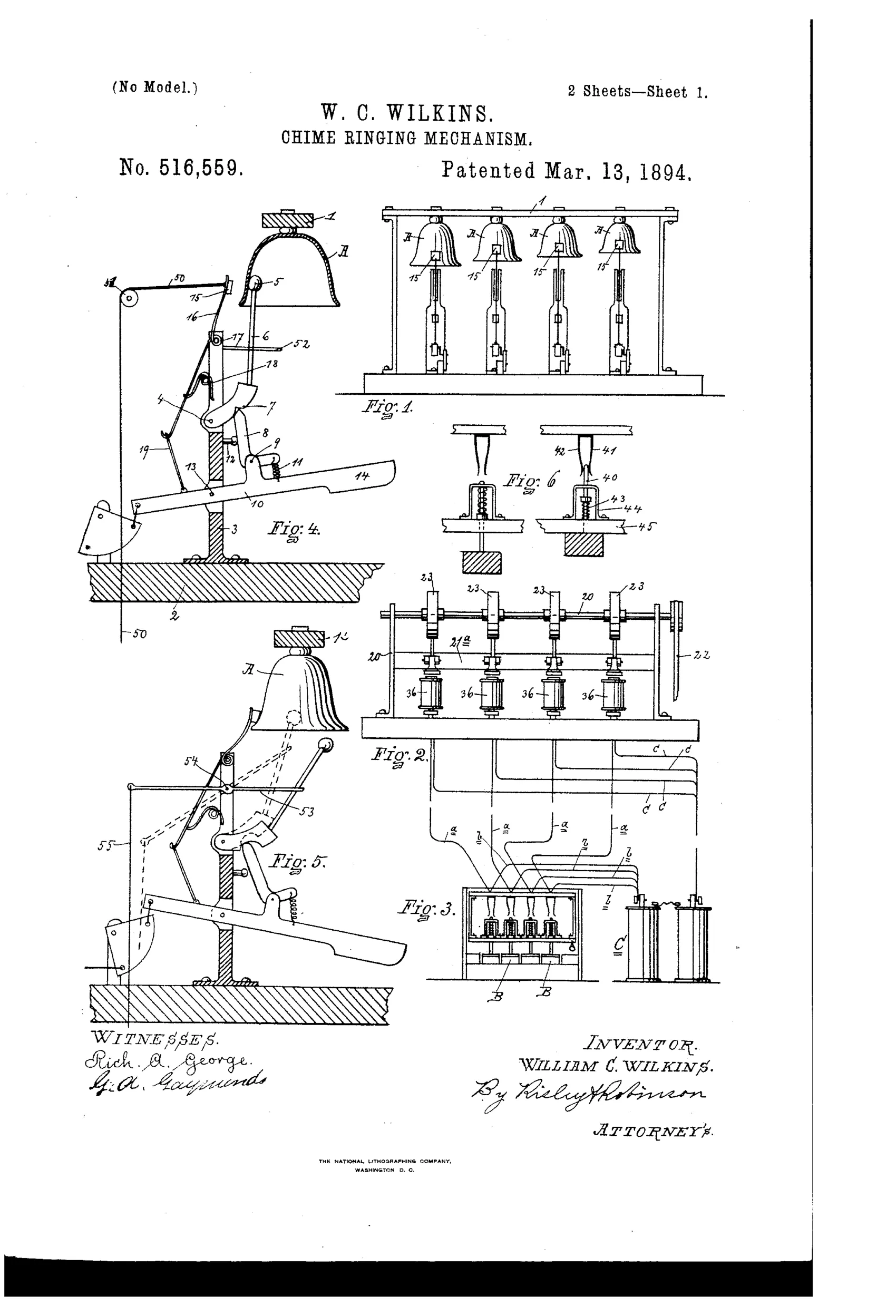
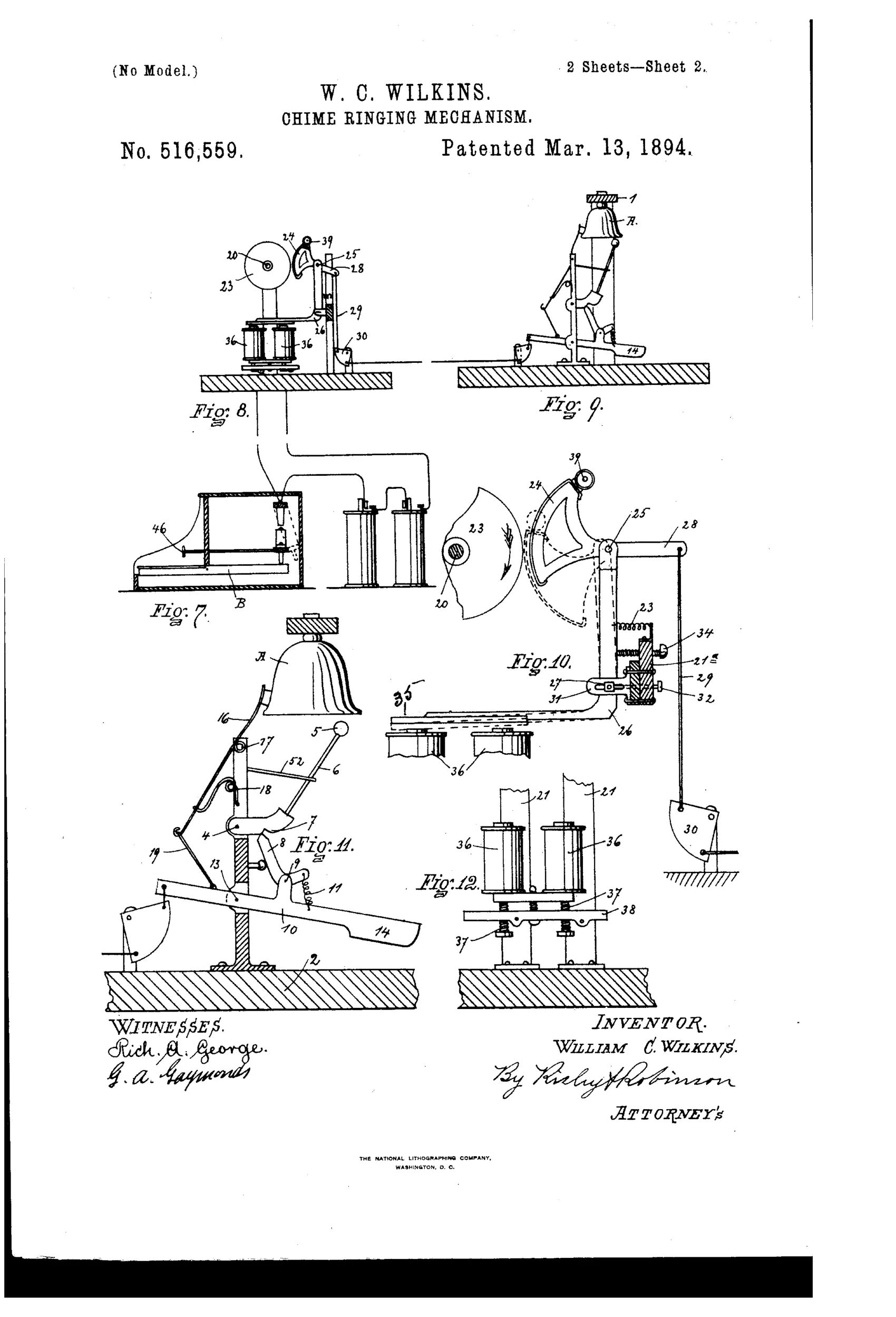
Electrically operated keyboard mechanism for ringing tower chimes
♫ How it works
A continuously rotating shaft carries a series of friction pulleys, one for each bell. Pressing a key on a keyboard closes an electric circuit through a battery to an electro-magnet, drawing down an armature on a bell-crank lever and swinging a friction segment into contact with its rotating pulley. This motion is transmitted through a connecting linkage to a pivoted lever arm that both strikes the bell hammer against the inside of the bell and simultaneously lifts a spring-pressed damper off the bell's rim. Releasing the key breaks the circuit, the armature is released, and springs and a counter-weighted lever return all parts to normal position while the damper falls back to silence the bell.
♫ What was claimed
“In a chime ringing mechanism a number of bells a hammer arranged to strike each bell, a rotating shaft having a series of friction pulleys mounted thereon, a corresponding series of bell crank levers each independently adjustably pivoted to a support adjacent to the angle therein and adapted to swing in the plane of the pulley, one arm thereof extending up the side and the other under the pulley, a friction segment pivoted in the upright arm of each and adapted to engage the pulley, an armature mounted on the other arm, a series of electro magnets mounted on a support in positions to act on the armatures of the several levers a set of keys and circuit making and breaking devices in the independent circuits with the several electro magnets operated by the keys and operating connections between the segments and several hammers for the various bells combined, substantially as set forth.”
In plain English: Each bell has its own hammer, bell-crank lever with a friction segment riding a common rotating shaft, and electro-magnet controlled by a key, so pressing a key engages that bell's friction drive to swing the hammer and strike the bell.
♫ In the inventor’s words
“The keys could be operated by a "barrel organ."”— William C. Wilkins, from the specification
Fate unknown
The assignment suggests commercial intent, but no installed example is documented; a church record or trade-catalog listing from Utica would settle it.
♫ Commentary
The problem Wilkins is solving is real: an electro-magnet strong enough to swing a bell hammer directly would need a battery the size of a wagon. His answer is a servo, decades before anyone used the word. The magnet does almost no work — it merely tips a friction segment against a pulley on a continuously rotating shaft, and the shaft's motor does the heavy lifting, hauling the hammer around through the linkage. Press a key, the segment grabs, the bell rings; release, springs let go. Each bell gets its own pulley on the common shaft, so the keyboard is genuinely polyphonic.
The detail worth studying in Figs. 4 and 5 is the damper. The same stroke that drives the hammer against the bell's inside also lifts a spring-pressed pad off the bell's rim, and when the key is released the pad drops back and silences it. That gives the player note lengths, not just strikes — closer to a carillon clavier than a doorbell, and unusual thought for 1894.
The specification even remarks that the keys could be worked by a barrel organ, which puts this squarely in our mechanical-music family: an automated chime is only a pinned barrel away. Whether Fish, the assignee, ever put one in a tower is another matter; church chime installations of the era were bespoke, and this design would demand constant adjustment of friction segments and battery contacts.
Commentary by Claude, The Talking Machine Patent Archive’s resident enthusiast