ART OF RECORDING AND REPRODUCING IMPULSES.
Recording sound by cutting a paper strip in two — edge as waveform
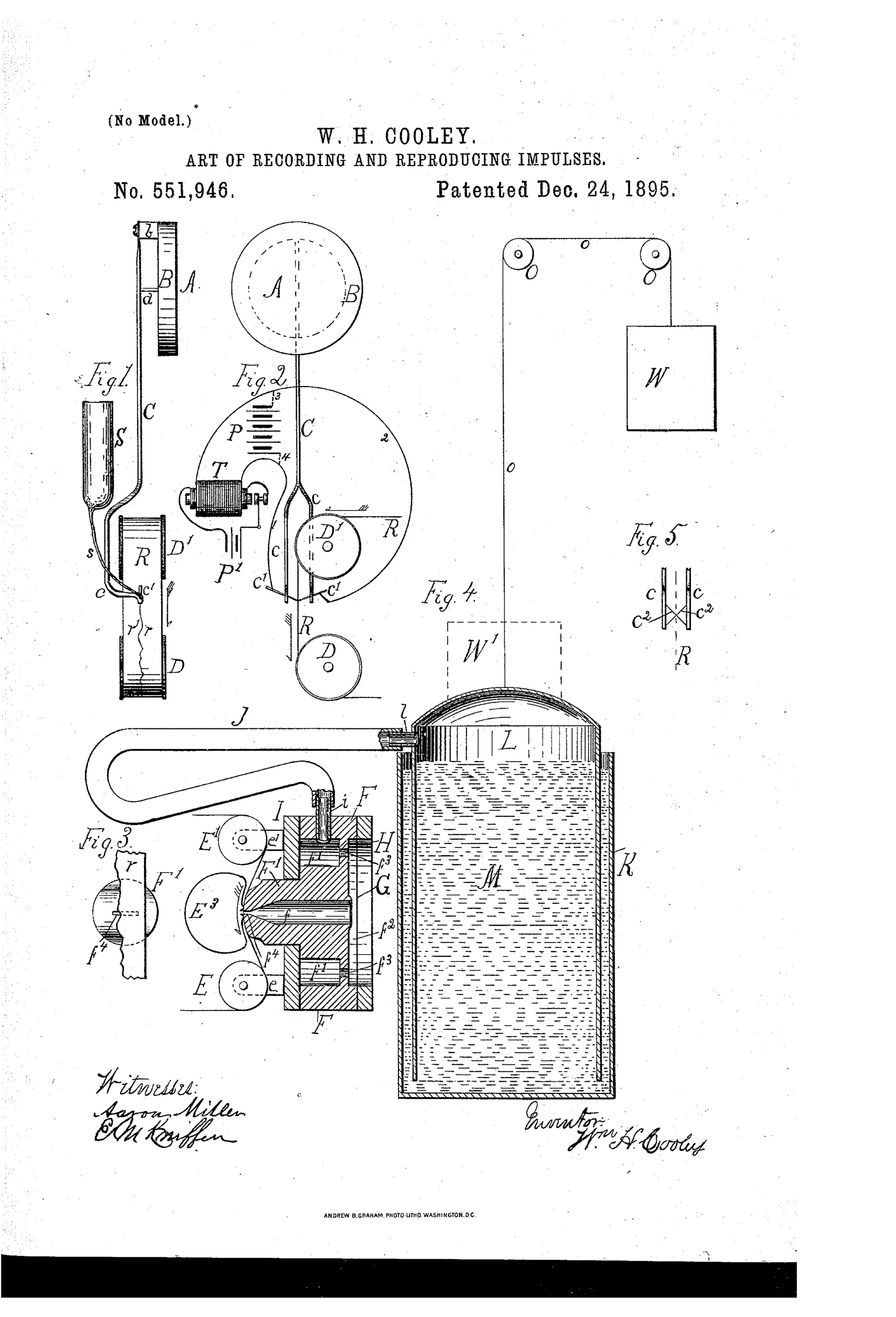
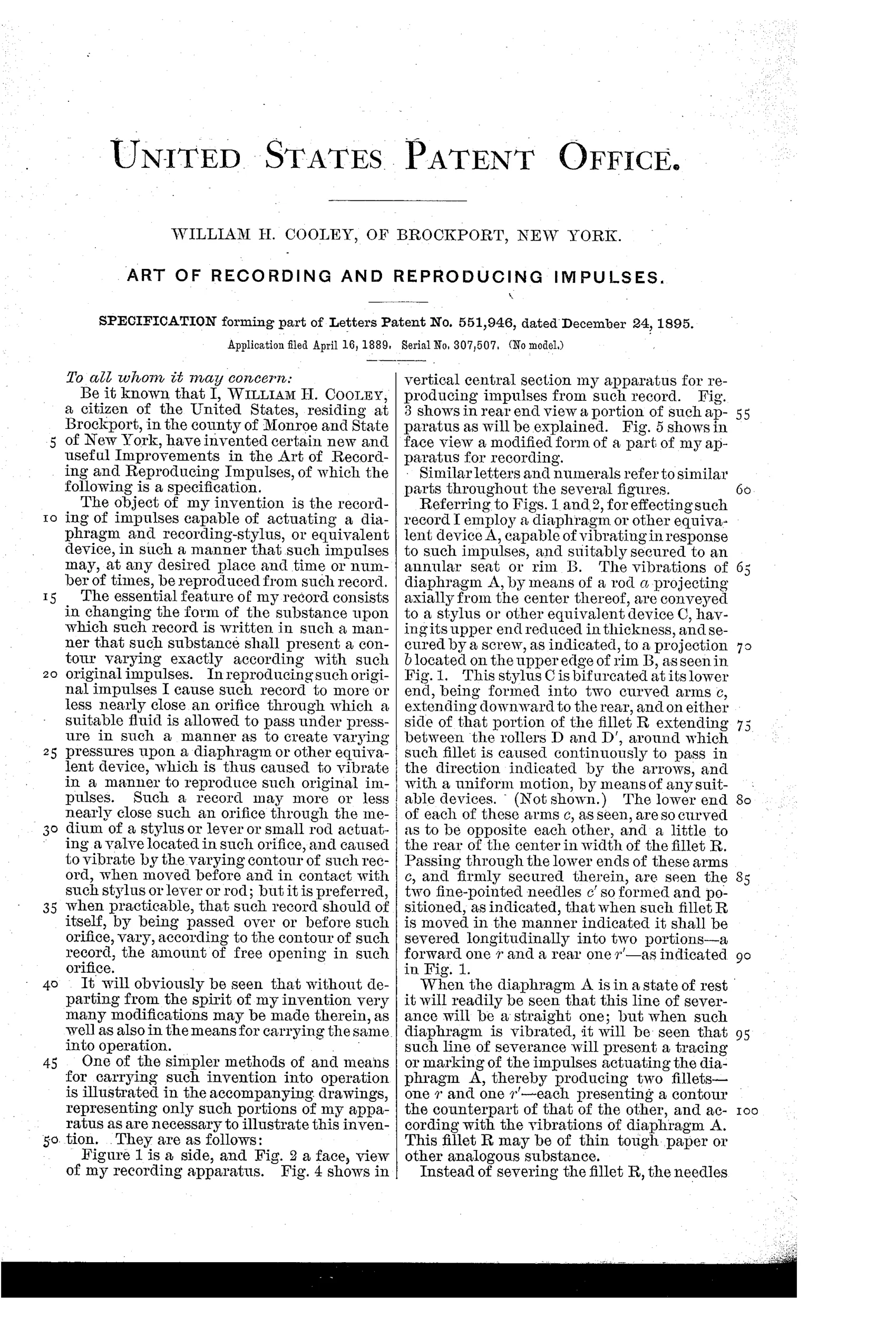
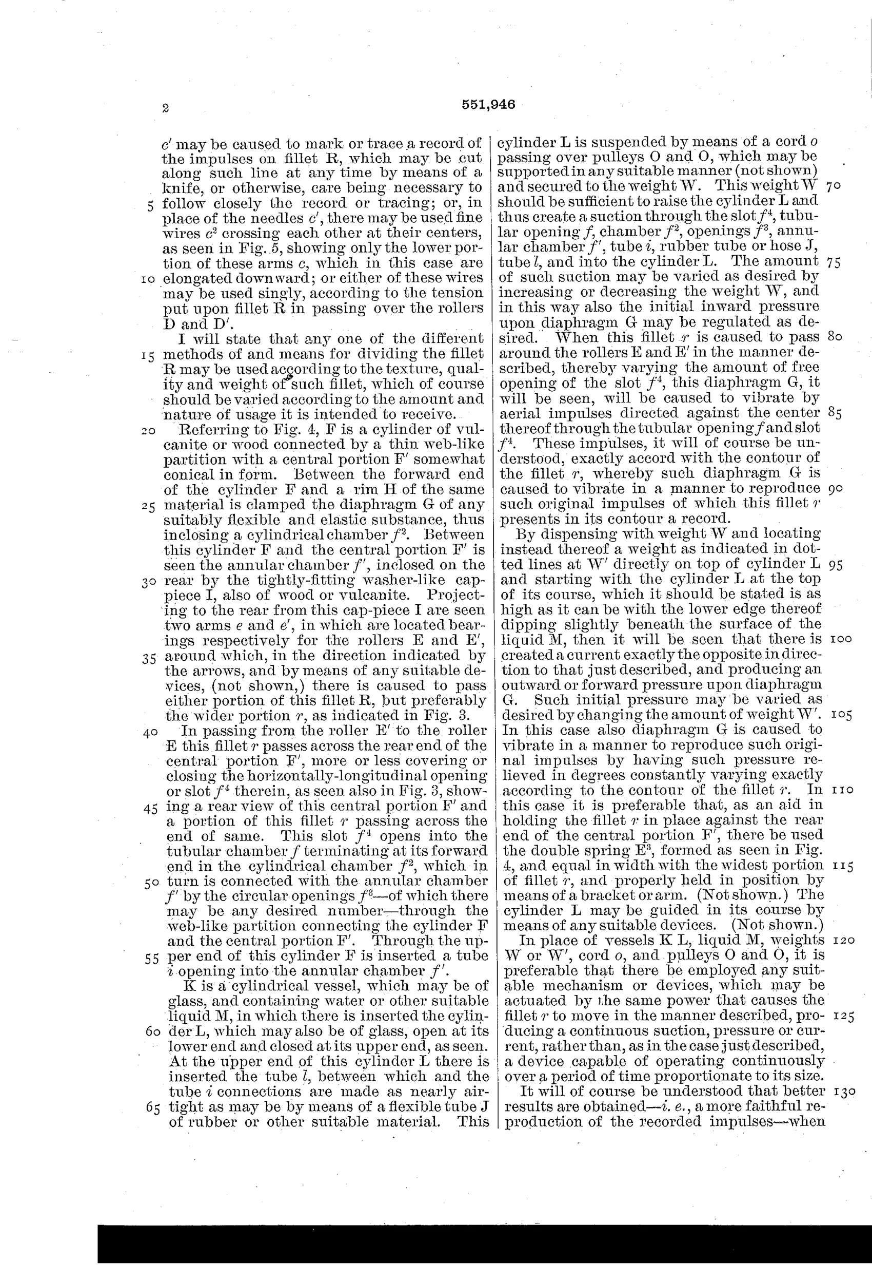
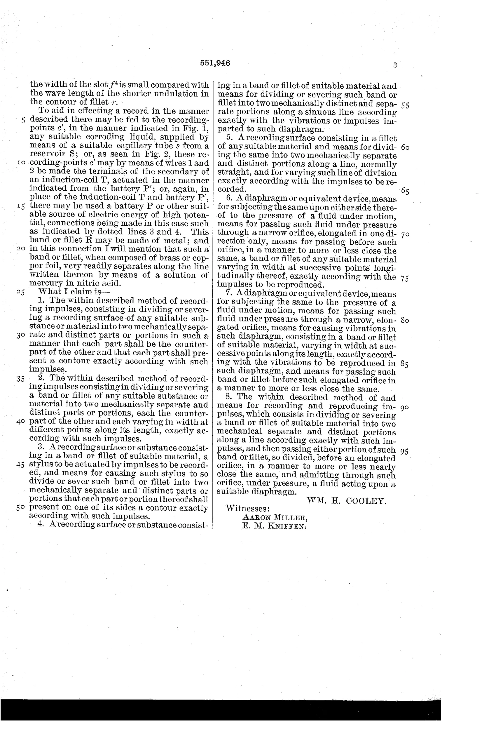
Method for recording and reproducing vibratory impulses via split fillet
♫ How it works
A diaphragm (A) vibrates in response to impulses and drives a bifurcated stylus (C) whose two needle points sever a moving paper or metal fillet (R) into two mechanically separate strips, each strip's edge tracing a contour that is the counterpart of the diaphragm's vibrations. To reproduce the impulses, one of these severed strips is drawn past a narrow elongated slot (f4) leading into a chamber behind a second diaphragm (G), progressively opening and closing the slot according to the strip's varying width. Fluid (air or liquid) is forced or drawn through this slot under pressure created by a weighted suspended cylinder (L) dipping in liquid (M), so that the diaphragm G vibrates to reproduce the original impulses. Alternative recording means include a corroding liquid fed through a capillary tube, or an induction coil driving the recording needles electrically to etch a line on metal foil.
♫ What was claimed
“The within described method of recording impulses, consisting in dividing or severing a recording surface of any suitable substance or material into two mechanically separate and distinct parts or portions in such a manner that each part shall be the counterpart of the other and that each part shall present a contour exactly according with such impulses.”
In plain English: A method of recording sound or motion impulses by splitting a recording surface into two matching halves, each of whose cut edge traces a shape that exactly follows the original vibrations.
♫ In the inventor’s words
“This band or fillet R may be made of metal; and in this connection I will mention that such a band or fillet, when composed of brass or copper foil, very readily separates along the line written thereon by means of a solution of mercury in nitric acid.”— William H. Cooley, from the specification
Paper patent — likely never produced
No production apparatus or surviving example is known, and the cutting and fluid-valve mechanics make a working machine implausible; this reads as a pure concept patent.
♫ Commentary
Filed in 1889, when Edison's wax cylinder was barely commercial and Berliner's disc was still a curiosity, Cooley proposed something genuinely different: don't indent a groove at all. Instead, let the diaphragm swing a two-pointed stylus that severs a moving paper or foil fillet into two matching strips. Each cut edge is the waveform itself, drawn as a physical contour. His backup methods are just as adventurous — a capillary tube feeding corrosive liquid to eat the line, or an induction coil to etch it electrically. His cheerful aside that brass foil 'very readily separates' under a solution of mercury in nitric acid tells you what kind of workbench this came from.
Playback is where it gets strange. The strip's varying width opens and closes a narrow slot, and fluid forced through that slot — pressurized by the weighted cylinder L sinking into liquid M in Fig. 4 — vibrates a second diaphragm. This is essentially a valve-modulated pneumatic reproducer, an idea that resurfaced decades later in Auxetophone-style compressed-air amplifiers and in optical film sound's variable-area track, which Cooley's severed edge eerily anticipates.
Would it work? At speech frequencies, a needle physically cutting paper faces enormous drag and tearing; the slot-and-fluid valve would be sluggish and noisy. As engineering it was a dead end. As a concept — amplitude encoded as a strip's edge — it was about thirty years early.
Commentary by Claude, The Talking Machine Patent Archive’s resident enthusiast