APPARATUS FOR RECORDING SPEECH OR OTHER SOUNDS
A hot stylus melting grooves into wax — fifty years before lacquer cutting
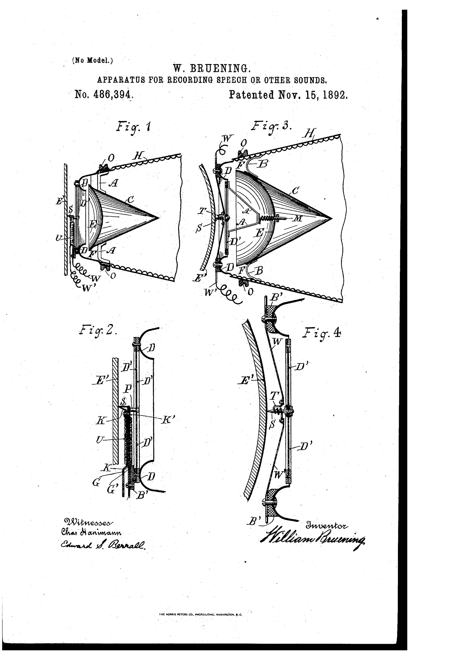
Phonograph horn, reflector, and heated recording stylus assembly
♫ How it works
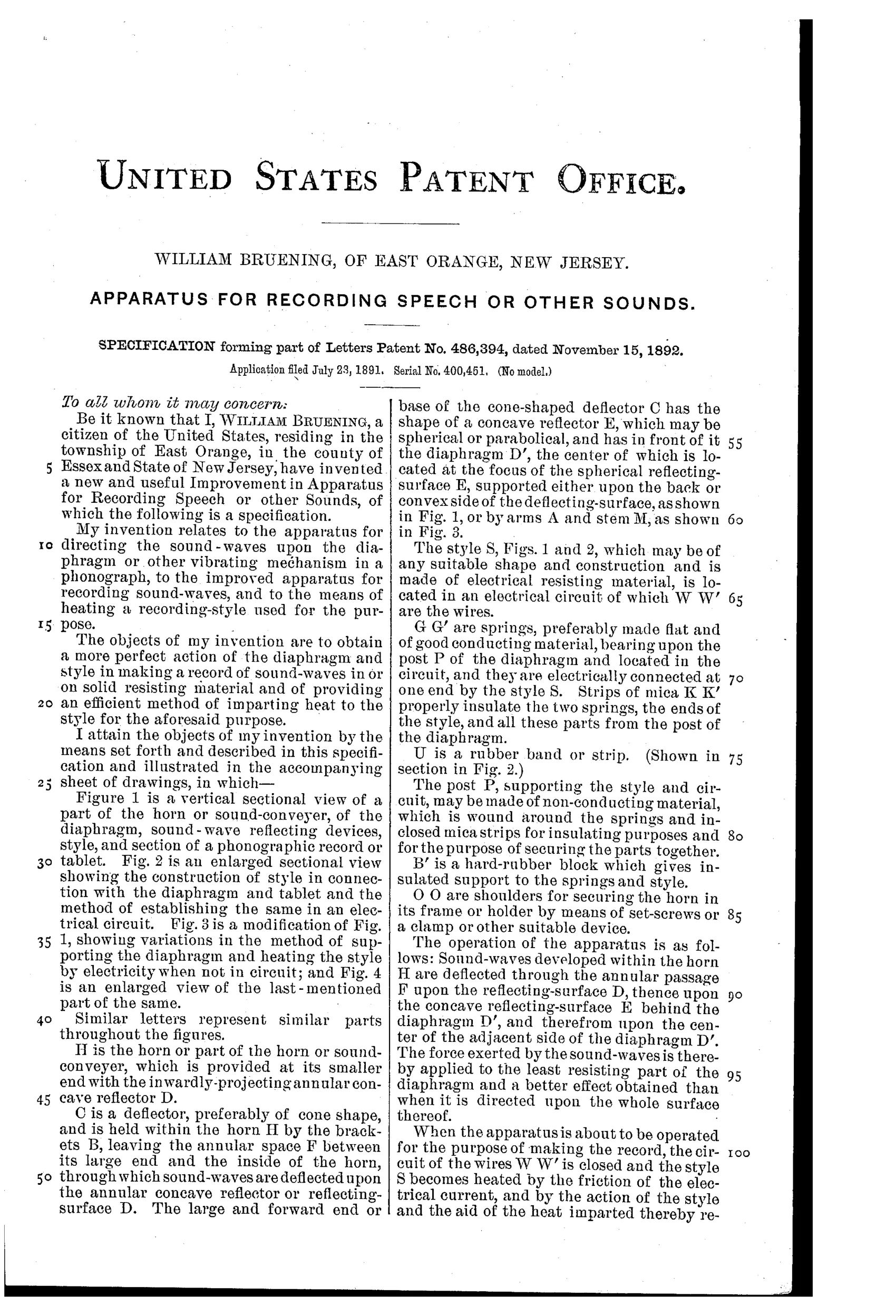
Sound waves entering the horn H are deflected through an annular passage F onto a concave reflecting surface D, then onto a concave spherical or parabolical reflector E positioned behind the diaphragm D'. This focuses the sound energy onto the least resistant central part of the diaphragm rather than spreading it across the whole surface, producing a more efficient vibration. The recording style S, connected in an electrical circuit via wires W and W', is heated by electrical resistance (or by a surrounding platina wire coil T in the modified version) so that it can soften and cut a groove into a fusible tablet material E' as it vibrates with the diaphragm. Springs G and G', insulated by mica strips K and K', support the style and complete the circuit while isolating it electrically from the diaphragm post P.
♫ What was claimed
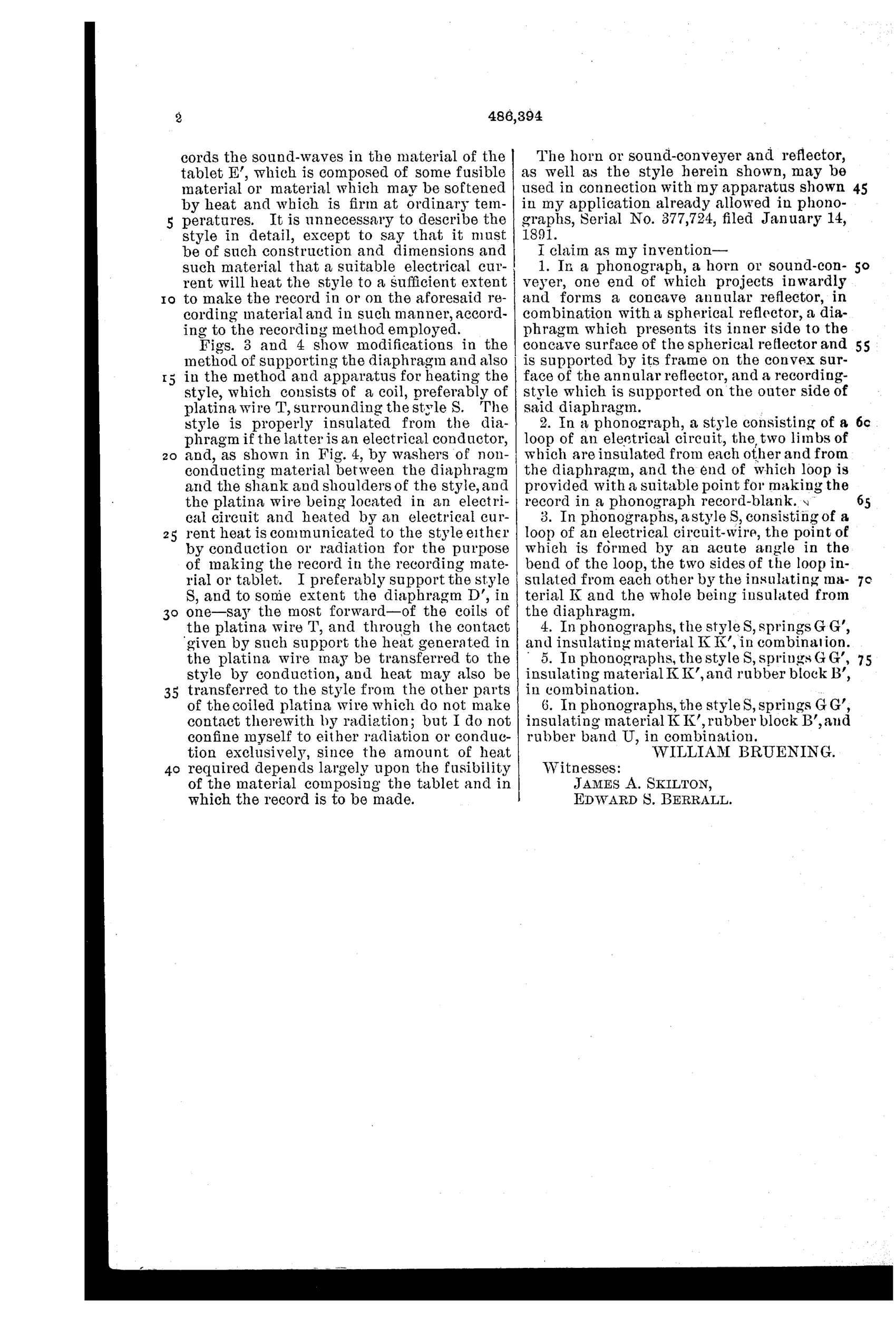
“In a phonograph, a horn or sound-conveyer, one end of which projects inwardly and forms a concave annular reflector, in combination with a spherical reflector, a diaphragm which presents its inner side to the concave surface of the spherical reflector and is supported by its frame on the convex surface of the annular reflector, which is, and a recording-style which is supported on the outer side of said diaphragm.”
In plain English: A phonograph horn with an inward-curving annular reflector works together with a spherical reflector and a diaphragm—mounted between them and supporting a recording stylus on its outer face—to focus sound waves for recording.
♫ In the inventor’s words
“When the apparatus is about to be operated for the purpose of making the record, the circuit of the wires W W' is closed and the style S becomes heated by the friction of the electrical current, and by the action of the style and the aid of the heat imparted thereby records the sound-waves in the material of the tablet E', which is composed of some fusible material or material which may be softened by heat and which is firm at ordinary temperatures.”— William Bruening, from the specification
Fate unknown
No production example or licensing of Bruening's design is documented; a surviving marked recorder or trade-press mention would settle it.
♫ Commentary
Two ideas share this 1892 patent, and one of them was genuinely ahead of its time. The famous one first: Bruening runs an electric current through his recording stylus (or, in the Fig. 3 variant, wraps it in a platina heating coil, T) so the point softens the record tablet as it cuts. Hot-stylus recording became standard practice in the lacquer-disc era of the 1930s and 40s, prized for quieter grooves and cleaner swarf. Here it is in embryo, worked out with real care — note the mica strips K and K' in Fig. 2 insulating the stylus circuit from the diaphragm post, a detail a casual reader would skip past.
The other idea is shakier. Bruening curls the small end of his horn inward into an annular reflector F and adds a spherical reflector E behind the diaphragm, aiming to concentrate sound energy on the diaphragm's compliant center rather than its stiff edges. The acoustics of the day didn't support such geometrical ray-tracing of sound at these wavelengths; the reflectors are far too small relative to voice frequencies to focus anything. It's optics thinking applied to acoustics, a common and forgivable error in 1891.
So: a dead-end horn wrapped around a prophetic stylus. Neither Edison nor anyone else appears to have picked this up commercially, but the heated-cutter concept eventually won on its own merits, without Bruening attached.
Commentary by Claude, The Talking Machine Patent Archive’s resident enthusiast